volkswagen Workshop Repair Guides

Volkswagen Workshop Service and Repair Manuals

Checking coolant temperature sender > < Checking air mass meter
Simos injection and ignition system
Checking throttle valve control part

Note:

If the throttle valve control part J338 is removed and installed or replaced the basic setting must be performed .

Special tools, testers and auxiliary items

  • ◆ Fault reader V.A.G 1551 or vehicle system tester V.A.G 1552 with cable V.A.G 1551/3
  • ◆ Test box V.A.G 1598/18
  • ◆ Hand multimeter V.A.G 1526 or multimeter V.A.G 1715
  • ◆ Adapter set V.A.G 1594
  • ◆ Current flow diagram

Checking voltage supply

 
N24-0170
  • ‒ → Separate 8 pin connector to throttle valve control part.
  • ‒ Connect multimeter using aux. cables from V.A.G 1594 to measure voltage at contacts 3+7 of connector.
  • ‒ Switch on ignition.
         Specification: 9.0...14.5 V
  • ‒ Connect multimeter using aux. cables from V.A.G 1594 to measure voltage at contacts 4+7 of connector.
         Specification: 4.0...6.0 V
  • ‒ Switch off ignition.

If the specifications are not attained:

 
N24-0165
  • ‒ → Connect test box V.A.G 1598/18 to control unit wiring loom.
 
N24-0170
  • ‒ → Check wiring between test box and 8 pin connector for open circuit according to current flow diagram.
         Contact 3+socket 18
         Contact 4+socket 41
         Contact 7+socket 35
         Wire resistance: Max. 1.5 ω
  • ‒ Check wiring at 8 pin connector for short to one another.
         Contact 7+socket 18
         Contact 7+socket 41
         Contact 4+socket 35
         Specification: ∞ω
  • ‒ Additionally check wiring for sender earth -socket 35- for short to vehicle earth.
         Sockets 01 + 35
         Socket 35 + vehicle earth
         Specification: ∞ω

If no wiring fault is detected:

  • ‒ Renew Simos control unit (J361)
    , item 4 .

Checking operating condition

  • ‒ Connect fault reader V.A.G 1551 (V.A.G 1552) and select engine electronics control unit with the "Address word" 01. When doing this the ignition must be switched on.
    (Connecting fault reader and selecting engine electronics control unit => Page 01-3 .)
 
→ Indicated on display:
Rapid data transfer     HELP
Select function XX
  • ‒ Press keys 0 and 8 for the function "Read measured value block" and confirm entry with Q key.
 
→ Indicated on display:
Read measured value block     HELP
Input display group number XX
  • ‒ Press keys 0 and 7 for "Display group number 07" and confirm entry with Q key.
 
→ Indicated on display:
(1...4 = Display zones)
Read measured value block 1     ⇒
     1     2     3     4
  • ‒ Check throttle valve control part operating condition in display zone 4.
         Specification: 00000000

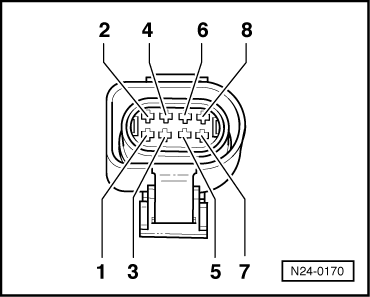
Significance of figures in 8 digit number block for throttle valve control unit.

Significance when display position = 1

x

x

x

x

x

x

x

x

Throttle valve control part operating condition (display group 07)

1

Mechanical emergency running

1

Not relevant

1

Adaptation required

1

Adaptation required

1

Not relevant

1

Adaptation terminated (battery voltage too low)

1

Adaptation terminated (time exceeded)

1

Idling speed switch open

If the specifications are not obtained:

  • ‒ Perform basic setting => Page 24-37
  • ‒ Repeat check.

Checking idling switch

  • ‒ Connect fault reader V.A.G 1551 (V.A.G 1552) and select engine electronics control unit with the "Address word" 01. When doing this the ignition must be switched on.
    (Connecting fault reader and selecting engine electronics control unit => Page 01-3 .)
 
→ Indicated on display:
Rapid data transfer     HELP
Select function XX
  • ‒ Press keys 0 and 8 for the function "Read measured value block" and confirm entry with Q key.
 
→ Indicated on display:
Read measured value block     HELP
Input display group number XX
  • ‒ Press keys 0 and 1 for "Display group number 01" and confirm entry with Q key.
 
→ Indicated on display:
(1...4 = Display zones)
Read measured value block 1     ⇒
     1     2     3     4
  • ‒ Check idling switch at idling stop in display zone 4.
  • 4th position from left must display 0
         Display: 00000000
  • ‒ Slowly open throttle valve.
  • 4th position from left must display 1
         Display: 00010000
  • ‒ Switch off ignition.

If the specifications are not obtained:

 
N24-0165
  • ‒ → Connect test box V.A.G 1598/18 to control unit wiring loom.
  • ‒ With throttle valve closed connect multimeter to measure resistance at test box sockets 18+35.
         Specification: max. 1.5 ω
  • ‒ Slowly open throttle valve.
         Specification: ∞ω

If the specifications are not obtained:

 
N24-0170
  • ‒ → Separate 8 pin connector to throttle valve control part.
  • ‒ Check wiring between test box and 8 pin connector for open circuit according to current flow diagram.
         Contact 3+socket 18
         Contact 7+socket 35
         Wire resistance: Max. 1.5 ω
  • ‒ Check wiring at 8 pin connector for short to one another.
         Contact 7+socket 18
         Specification: ∞ω
  • ‒ Additionally check wiring for sender earth -socket 35- for short to vehicle earth.
         Sockets 01 + 35
         Socket 35 + vehicle earth
         Specification: ∞ω

If no wiring fault is detected:

  • ‒ Replace throttle valve control part (J338).

Checking throttle valve potentiometer

  • ‒ Connect fault reader V.A.G 1551 (V.A.G 1552) and select engine electronics control unit with the "Address word" 01. When doing this the ignition must be switched on.
    (Connecting fault reader and selecting engine electronics control unit => Page 01-3 .)
 
→ Indicated on display:
Rapid data transfer     HELP
Select function XX
  • ‒ Press keys 0 and 8 for the function "Read measured value block" and confirm entry with Q key.
 
→ Indicated on display:
Read measured value block     HELP
Input display group number XX
  • ‒ Press keys 0 and 3 for "Display group number 03" and confirm entry with Q key.
 
→ Indicated on display:
(1...4 = Display zones)
Read     measured value block 3     ⇒
     1     2     3     4
  • ‒ Read-off throttle valve angle in display zone 3.
         Specification ADY, AGG: 2.5...6.5 <°
         Specification AFT: 3.0...4.5 <°
  • ‒ Slowly open throttle valve and watch angle display in display zone 3.
    The figure must increase uniformly over
         the complete range.
  • ‒ Press ⇒key.
  • ‒ Press keys 0 and 6 for the function "End output" and confirm entry with the Q key.
  • ‒ Switch off ignition.

Note:

The displayed figure is dependent on the tolerances of the throttle valve potentiometer and does not correspond to the actual opening angle. The maximum permissible displayed figure is 99.5 <°.

If the figure does not increase uniformly:

  • ‒ Replace throttle valve control part (J338).
 
N24-0165

If the display shows constant 2 <°:

  • ‒ → Connect test box V.A.G 1598/18 to control unit wiring loom.
  • ‒ Check wire for short to earth.
         Sockets 01+40
         Specification: ∞ω
  • ‒ Additionally check wiring for sender earth -socket 35- for short to vehicle earth.
         Sockets 01 + 35
         Socket 35 + vehicle earth
         Specification: ∞ω
  • ‒ Switch ignition on.
  • ‒ Check wire for short to positive, to do this connect multimeter to measure voltage at test box sockets 01+40
         note voltage if voltage present
  • ‒ Switch off ignition.

Continuation if voltage is present:

If voltage of about 5 V was present:

 
N24-0170
  • ‒ → Separate 8 pin connector to throttle valve control part.
  • ‒ Switch ignition on.
  • ‒ Check wiring at 8 pin connector contacts 4+5 for short to one another according to current flow diagram.

If the voltage was approx. battery voltage:

  • ‒ Check wire at 8 pin connector contact 5 for short to battery positive according to current flow diagram.

Continuation if no voltage is present:

 
N24-0170
  • ‒ → Separate 8 pin connector to throttle valve control part.
  • ‒ Check wiring between test box and 8 pin connector for open circuit according to current flow diagram.
         Contact 5+socket 40
         Wire resistance: Max. 1.5 ω

If no wiring fault is detected:

  • ‒ Replace throttle valve control part (J338).

Checking throttle valve positioner and throttle valve positioner potentiometer

Test conditions

  • ● Coolant temperature at least 80 °C

Test sequence

  • ‒ Connect fault reader V.A.G 1551 (V.A.G 1552) and select engine electronics control unit with the "Address word" 01. When doing this the engine must be running at idling speed.
    (Connecting fault reader and selecting engine electronics control unit => Page 01-3 .)
 
→ Indicated on display:
Rapid data transfer     HELP
Select function XX
  • ‒ Press keys 0 and 8 for the function "Read measured value block" and confirm entry with Q key.
 
→ Indicated on display:
Read measured value block     HELP
Input display group number XX
  • ‒ Press keys 0 and 3 for "Display group number 03" and confirm entry with Q key.
 
→ Indicated on display:
(1...4 = Display zones)
Read measured value block 3     ⇒
     1     2     3     4
  • ‒ Check throttle valve positioner duty cycle at idling stop in display zone 4.
         Specification ADY, AGG: 6...21 %
         Specification AFT: 13...20 %

If the specification is not obtained:

 
N24-0165
  • ‒ → Connect test box V.A.G 1598/18 to control unit wiring loom.
  • ‒ With throttle valve closed connect multimeter to measure resistance at test box sockets 25+30.
         Specification: 3...200 ω

If the specification is not obtained:

 
N24-0170
  • ‒ → Separate 8 pin connector to throttle valve control part.
  • ‒ Check wiring between test box and 8 pin connector for open circuit according to current flow diagram.
         Contact 1+socket 30
         Contact 2+socket 25
         Contact 7+socket 35
         Contact 8+socket 28
         Wire resistance: Max. 1.5 ω
 
N24-0170
  • ‒ → Check wiring at 8 pin connector for short to one another.
         Contact 1+socket 25
         Contact 1+socket 28
         Contact 1+socket 35
         Contact 2+socket 28
         Contact 2+socket 35
         Contact 7+socket 28
         Specification: ∞ω
  • ‒ Additionally check wiring for sender earth -socket 35- for short to vehicle earth.
         Sockets 01 + 35
         Socket 35 + vehicle earth
         Specification: ∞ω

If no wiring fault is detected:

  • ‒ Replace throttle valve control part (J338).
<SOURCEMARKET> </SOURCEMARKET> <SOURCESYSTEM> </SOURCESYSTEM>

Checking coolant temperature sender > < Checking air mass meter