
Passat (B3)
| Repairing drive shaft |
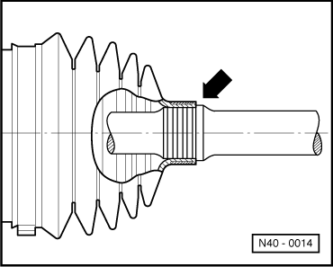
| Drive shafts on vehicles with Plus running gear have shorter and finer splines on the outer joint. A 12-point nut is used to secure to wheel bearing. |
| The splines of the outer joint and the wheel hub are locked with locking compound -D 185 400 A2- on vehicles with Plus running gear. |
| Removing and installing drive shaft: |
| t | Vehicles with basic running gear → Chapter. |
| t | Vehicles with Plus running gear → Chapter. |
 Note
Note| t | Greasing: outer constant velocity joint 100 g G-6.3, inner constant velocity joint 110 g G-6.3 |
| t | Greasing outer joint: press half of the grease into the joint and the other half evenly into the bellows. |
| t | Greasing inner joint: press half of the grease into the joint from both sides and the other half evenly into the bellows. |
| t | Regrease joint if required when renewing boot. |
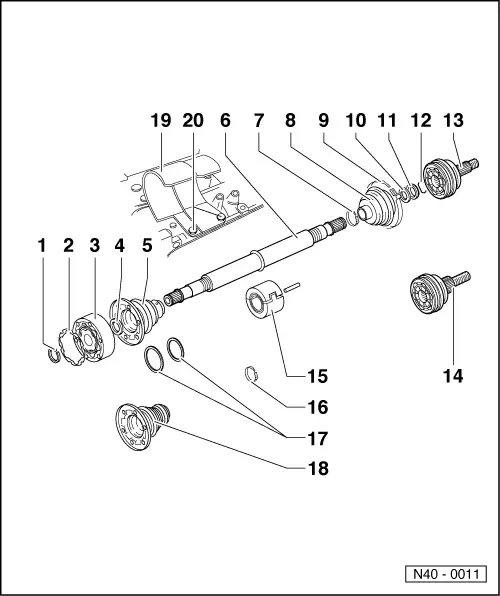
| 1 - | Circlip |
| q | Renew. |
| q | Remove and install with circlip pliers -VW 161 A-. |
| 2 - | Gasket |
| q | Renew: Pull off protective foil and stick onto joint. Only 100 mm Ø constant velocity joints. |
| 3 - | Inner constant velocity joint, 100 mm Ø |
| q | Renew only complete. |
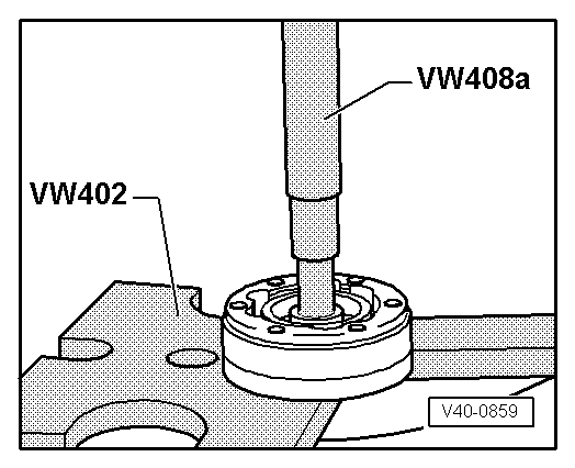
| q | Pressing off → Fig.. |
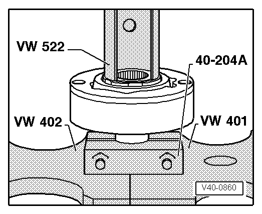
| q | Pressing on → Fig.. |
| q | Greasing → Chapter. |
| q | Checking → Chapter. |
| 4 - | Dished spring |
| q | Splined on internal Ø. |
| q | Installation position: larger Ø (concave side) contacts constant velocity joint. |
| 5 - | Joint protective boot for 100 mm Ø constant velocity joint |
| q | Rubber version. |
| q | With vent hole. |
| q | Check for splits and chafing. |
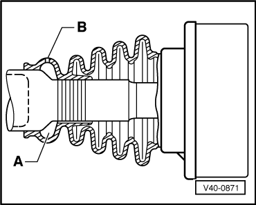
| q | Installation position for left shaft → Fig.. |
| q | Installation position for right shaft → Fig.. |
| q | Coat cap with D3. |
| q | Drive off with drift. |
| 6 - | Drive shaft |
| q | Left full shaft (not illustrated). |
| q | Right tubular shaft. |
| 7 - | Clamp |
| q | Renew. |
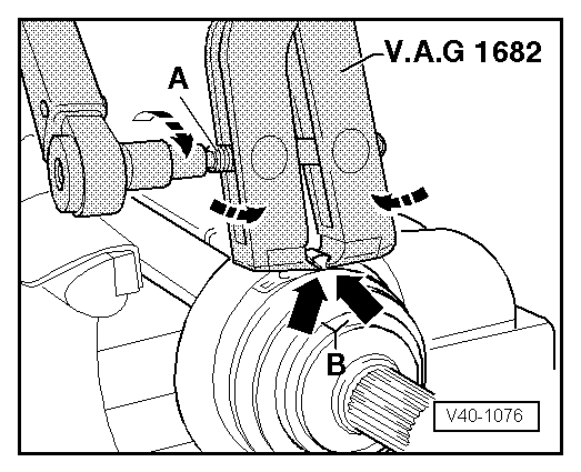
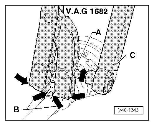
| q | Tensioning → Fig. and → Fig.. |
| 8 - | Joint protective boot for 90 mm Ø constant velocity joint |
| q | Polyester elastomer version. |
| q | Check for splits and chafing. |
| q | Allow air to enter joint protective boot briefly to balance pressure before tightening small clamp in place → Fig.. |
| q | Installation position for left shaft, wheel side → Fig. and → Fig.. |
| q | Installation position for right shaft, wheel side → Fig.. |
| 9 - | Clamp |
| q | Renew. |
| q | Tensioning → Fig. and → Fig.. |
| 10 - | Dished spring |
| q | Outer Ø (concave side) contacts thrust washer. |
| 11 - | Thrust washer |
| 12 - | Circlip |
| q | Renew. |
| q | Insert in groove in shaft. |
| 13 - | 90 mm Ø outer constant velocity joint |
| q | Renew only complete. |
| q | Removing → Fig.. |
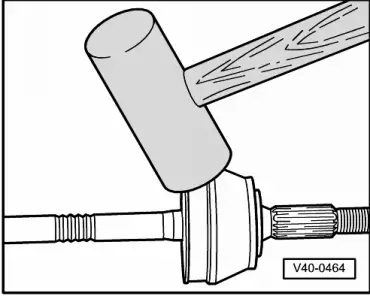
| q | Installing: drive onto shaft with plastic hammer until compressed retaining ring seats. |
| q | Greasing → Chapter. |
| q | Checking → Chapter. |
| 14 - | 90 mm Ø outer constant velocity joint |
| q | For vehicles with 16V or VR6 engine. |
| q | Larger diameter tapered splines. |
| q | Renew only complete. |
| q | Removing → Fig.. |
| q | Installing: drive onto shaft with plastic hammer until compressed retaining ring seats. |
| q | Greasing → Chapter. |
| q | Checking → Chapter. |
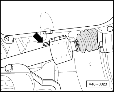
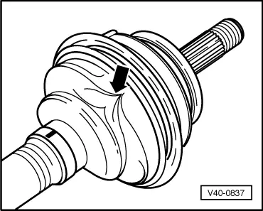
| 15 - | Vibration damper |
| q | Removing and installing → Fig.. |
| q | Installation position → Fig.. |
| q | Available as replacement part. |
| q | Is only installed on right tubular drive shaft. Exception: vehicles with 85 kW engine and 02C manual gearbox, only installed on left solid drive shaft. |
| 16 - | Clamp |
| q | Renew. |
| q | Tensioning → Fig. and → Fig.. |
| 17 - | Support ring |
| q | Only on rubber versions of joint protective boots. |
| q | Only gearbox side → Electronic parts catalogue “ETKA”. |
| 18 - | Joint protective boot for 100 mm Ø constant velocity joint |
| q | Polyester elastomer version. |
| q | Check for splits and chafing. |
| q | Allow air to enter joint protective boot briefly to balance pressure before tightening small clamp in place → Fig.. |
| 19 - | Protective cap |
| 20 - | Hexagon bolt, 35 Nm |
Note
|
|
|
|
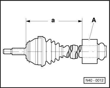
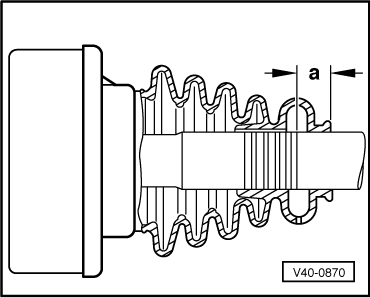
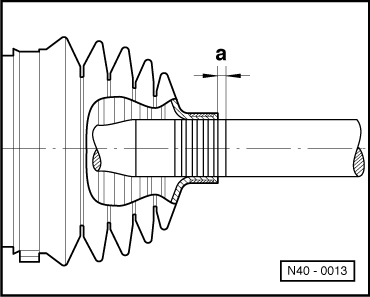
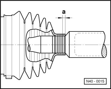
| Dimension “a” = | 521 ± 1 mm right shaft | |
| 264 ± 1 mm left shaft (if vibration damper is fitted) | ||
|
|
Note
|
|
Note
|
|
|
|
|
|
Note
|
|
|
|
Note
|
|
|
|
|
|