volkswagen Workshop Repair Guides

Volkswagen Workshop Service and Repair Manuals

Installing > < Removing and installing bonded rubber bush
Removing
Removing
   
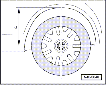
–  Measure distance -a- from centre of wheel to edge of wheel housing using, for example with a measuring tape
–  Note measured value. This is required for tightening the bolts for the rear axle on the mounting bracket.
–  Fit brake pedal depressor -V.A.G 1869/2-.
–  Raise vehicle to working height.
  Note
Treat mounting with rust remover (commercially available) and allow a period for treatment to take effect, if possible.
Vehicles with ABS
  N40-0640
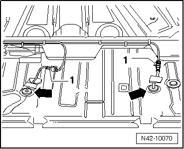
–  Fold-up rear seat bench and disconnect connection -1-.
–  Unclip rubber grommets -arrows- from floor panel and move speed sensor wiring from interior.
Continuation for all vehicles
–  Remove handbrake cables from retainers.
  N42-10070
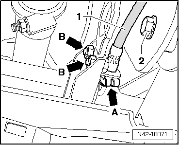
–  Disconnect brake lines -arrow A- and pull brake hose -1- out of retainer.
Vehicle with brake pressure regulator
–  Remove bolts -arrows B-.
Continuation for all vehicles
–  Position engine and gearbox jack -V.A.G 1383 A-.
–  Remove bolts -2- between mounting bracket and rear axle on each side.
–  Lower rear axle with engine and gearbox jack -V.A.G 1383 A-.
  N42-10071
–  Insert rear axle securing bolts -1- into mountng bracket again and secure.
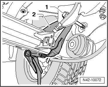
–  Secure rear axle on both sides with tensioning strap -T10038--2-.
  Note
Position engine and gearbox jack -V.A.G 1383 A- with universal gearbox support -V.A.G 1359/2- below suspension link (risk of accident due to falling parts on pulling out the bush).
  N42-10072
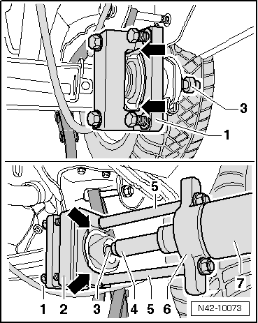
–  Fit pressure plate -VAS 6295/2--1- on inner bush and insert thrust bolt -VAS 6295/4--3- into bush from outside.
The cutters of the pressure plate -VAS 6295/2--1- must point towards the axle and must be securely inserted between bush and axle -arrows-.
–  Fit hydraulic cylinder -VAS 6178- with pressure plate -3111/5- behind the outer rubber-bonded bush.
The cutters of the pressure plate -3111/5--1- must point towards the axle and must be securely inserted between bush and axle -arrows-.
–  Secure pressure plate -3111/5- using bolts of pressure plate -VAS 6295/2-.
–  Press out bonded rubber bush.
1 - Pressure plate -VAS 6295/2-
2 - Pressure plate -3111/5-
3 - Thrust bolt -VAS 6295/4-
4 - Extension, 104 mm -VAS 6180/4-
5 - Pull rods -VAS 6295/3-
6 - Cylinder mounting -VAS 6295/1-
7 - Hydraulic press -VAS 6178-
  N42-10073
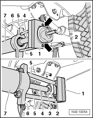
–  Fit hydraulic cylinder -VAS 6178- with pressure plate -3111/5- and press out rubber-bonded bush.
The cutters of the pressure plate -3111/5--1- must point towards the axle and must be securely inserted between bush and axle -arrows-.
1 - Pressure plate -3111/5-
2 - Thrust bolt -VAS 6295/4-
3 - Thrust pad -VAS 6295/6-
4 - Extension, 104 mm -VAS 6180/4-
5 - Pull rods -VAS 6295/3-
6 - Cylinder mounting -VAS 6295/1-
7 - Hydraulic press -VAS 6178-
  N42-10054

Installing > < Removing and installing bonded rubber bush