volkswagen Workshop Repair Guides

Volkswagen Workshop Service and Repair Manuals

Dismantling and assembling output shaft > < Dismantling and assembling input shaft
5-speed manual gearbox 085
Adjusting input shaft

(Determining thickness of shim for input shaft)

It is only necessary to readjust the input shaft when

  • ◆ Gearbox housing
  • ◆ Clutch housing
  • ◆ Input shaft

or the

  • ◆ Taper roller bearings

is renewed.

Adjustment overview

 
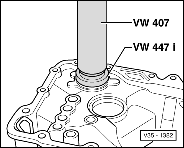
V35-1382
  • ‒ → Press taper roller bearing outer race, without shim, into gearbox housing onto stop.
  • ‒ Install input shaft in gearbox housing and assemble clutch housing. Tighten hexagon head bolts to 25 Nm.
 
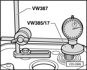
V35-0999
  • ‒ → Fit measuring appliance and D.T.I. (3 mm measuring range).
  • ‒ Before taking any measurements, rotate input shaft to allow bearings to settle. Set dial gauge to "O" with 1 mm preload.

Note:

This preparation is to be repeated for each subsequent measurement, otherwise the gauge will not return to the starting position.

  • ‒ Press input shaft in direction of D.T.I.
  • ‒ Read off and note clearance indicated on D.T.I. (example 1.21).

Note:

D.T.I. does not return to original position.

  • ‒ Determine thickness of shim from table => Page 35-16 .
  • ‒ Remove input shaft and pull taper roller bearing outer race out of clutch housing => Page 35-1 .
 
V35-1382
  • ‒ → Press taper roller bearing outer race together with selected shim (in example 1.20 mm) into clutch housing.
  • ‒ Insert input shaft into gearbox housing and assemble clutch housing and tighten hexagon head bolts to 25 Nm.

Table of shims

Measured

Shim

measured value
(mm)

Thickness (mm)

Part No.

... 0.68
0.68 ... 0.73
0.74 ... 0.78

0.65
0.70
0.75

085 311 391
085 311 391 A
085 311 391 B

0.79 ... 0.83
0.84 ... 0.88
0.89 ... 0.93

0.80
0.85
0.90

085 311 391 C
085 311 391 D
085 311 391 E

0.94 ... 0.98
0.99 ... 1.03
1.04 ... 1.08

0.95
1.00
1.05

085 311 391 F
085 311 391 G
085 311 391 H

1.09 ... 1.13
1.14 ... 1.18
1.19 ... 1.23

1.10
1.15
1.20

085 311 391 I
085 311 391 K
085 311 391 L

1.24 ... 1.28
1.29 ... 1.33
1.34 ... 1.38

1.25
0.65 + 0.65
0.65 + 0.70

085 311 391 M
085 311 391/391
085 311 391 + A

1.39 ... 1.43
1.44 ... 1.48
1.49 ... 1.53

0.70 + 0.70
0.70 + 0.75
0.75 + 0.75

085 311 391 A + A
085 311 391 A + B
085 311 391 B + B

1.54 ... 1.58
1.59 ... 1.63
1.64 ... 1.68
1.69 ... 1.75

0.75 + 0.80
0.80 + 0.80
0.80 + 0.85
0.85 + 0.85

085 311 391 B + C
085 311 391 C + C
085 311 391 C + D
085 311 391 D + D

 
V35-0999

Carrying out check measurement

  • ‒ → Install measuring appliance and D.T.I.
  • ‒ Rotate input shaft so that the taper roller bearings settle.
  • ‒ Zero D.T.I. with 1 mm of preload.
  • ‒ Press input shaft in direction of D.T.I.
  • ‒ Bearing play should be min. 0.01 ... max. 0.12 mm.

Note:

If the bearing clearance cannot be measured, but input shaft play is perceptible and the input shaft turns freely, the adjustment is acceptable.

  • ‒ Frictional moment max. 20 Ncm.

Dismantling and assembling output shaft > < Dismantling and assembling input shaft