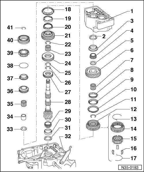
volkswagen Workshop Repair Guides

Volkswagen Workshop Service and Repair Manuals

Adjusting output shaft > < Adjusting input shaft
5-speed manual gearbox 085
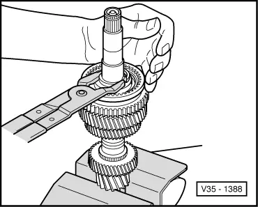
Dismantling and assembling output shaft
 
N35-0183

Notes:

  • ◆ When installing new gears or a new output shaft consult technical data
    .
  • ◆ If the output shaft or taper roller bearings have been renewed then carry out output shaft adjustment .
  • Gearbox housing
    • ◆ Due to the new washer (item 2 ) the bearing seat for the taper roller bearing outer race has been made deeper by 1 mm from build date 08 07 7. This does not apply to gearbox "DQW"
  • Washer
    • ◆ Always 1 mm thick
    • ◆ Installed from gearbox build date
      08 07 7, not applicable for gearbox "DQW"
 
N35-0183
  • Outer race/taper roller bearing
    • ◆ Pressing out of gearbox housing with output shaft => Page 34-88
    • ◆ Pressing in => Fig.1
  • Taper roller bearing inner race
    • ◆ Pressing off with 1st selector gear
      => Fig.2
    • ◆ Pressing on => Fig.19
  • Thrust washer
  • 1st selector gear
    • ◆ Installation position => Fig.18
  • Needle roller bearing
    • ◆ For 1st gear
  • Synchro-ring
    • ◆ (1st gear inner ring)
    • ◆ Checking for wear
      => Fig.10
    • ◆ Check lugs for scoring
    • ◆ Installation position => Fig.17
 
N35-0183
  • 1st gear outer ring
    • ◆ Insert in the synchro-ring (item 10 ), installation position => Fig.16
    • ◆ Renew if scored
  • 1st gear synchro-ring
    • ◆ Checking for wear
      => Fig.11
    • ◆ Assemble so that the recesses locate in the locking collar (item 12 ) locking pieces
  • Circlip
    • ◆ Pressing out => Fig.3
    • ◆ Inserting => Fig.9
  • 1st and 2nd gear locking collar with synchro-hub
    • ◆ Parts are paired
    • ◆ Pressing off => Fig.4
    • ◆ Assembling locking collar/synchro-hub => Fig.13 and Fig.14
    • ◆ Pressing on => Fig.15
 
N35-0183
  • Spring
  • Locking collar
  • Synchro-hub
  • Locking pieces (Qty. 3)
  • Spring
  • 2nd gear synchro-ring
    • ◆ Checking for wear
      => Fig.11
    • ◆ Installation position => Fig.12
  • 2nd gear outer ring
    • ◆ Insert in the synchro-ring (item20 )
    • ◆ Installation position => Fig.12
    • ◆ Renew if scored
 
N35-0183
  • Synchro-ring
    • ◆ (2nd gear inner ring)
    • ◆ Checking for wear
      => Fig.10
    • ◆ Check lugs for scoring
    • ◆ Installation position => Fig.12
  • 2nd gear
  • Circlip
    • ◆ Pressing out => Fig.3
    • ◆ Inserting => Fig.9
  • Needle roller bearing
    • ◆ For 2nd gear
  • 3rd gear
  • Circlip
    • ◆ Pressing out => Fig.3
    • ◆ Inserting => Fig.9
  • Circlip
    • ◆ Pressing out => Fig.3
    • ◆ Inserting => Fig.9
 
N35-0183
  • 4th gear
    • ◆ Marked groove points towards final drive teeth
  • Output shaft
    • ◆ Ensure correct ratio (number of teeth) => Page 00-3 .
    • ◆ Adjusting => Page 35-36
  • Taper roller bearing inner race
    • ◆ Pulling off => Fig.5
    • ◆ Pressing on => Fig.6
  • Outer race/taper roller bearing
    • ◆ Removing => Fig.7
    • ◆ Pressing in => Fig.8
  • Shim
    • ◆ For output shaft
    • ◆ Determining thickness
      => Page 35-36
  • Clutch housing
 
N35-0183
  • Thrust washer
    • ◆ Shoulder on thrust washer faces taper roller bearing
  • Sleeve for needle roller bearing
    • ◆ Pressing off with 1st selector gear
      => Fig.2
    • ◆ Driving on => Page 34-96
  • 5th selector gear needle roller bearing
  • Selector gear for 5th gear
  • 5th gear synchro-ring
  • Spring
    • ◆ Insert onto 5th gear synchro-ring
    • ◆ Renew when worn
  • 5th gear synchro-hub
    • ◆ Removing => from Page 34-80
 
N35-0183
  • 5th gear locking collar
    • ◆ Removing => from Page 34-80
  • Circlip
    • ◆ Always renew
    • ◆ Determining thickness => Page 34-98
 
V35-1385

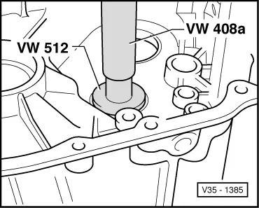
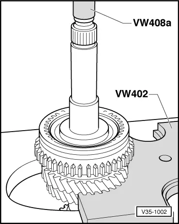
→ Fig.1     Pressing in taper roller bearing outer race

 
N35-0182

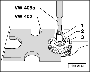
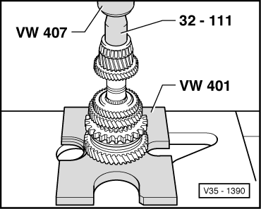
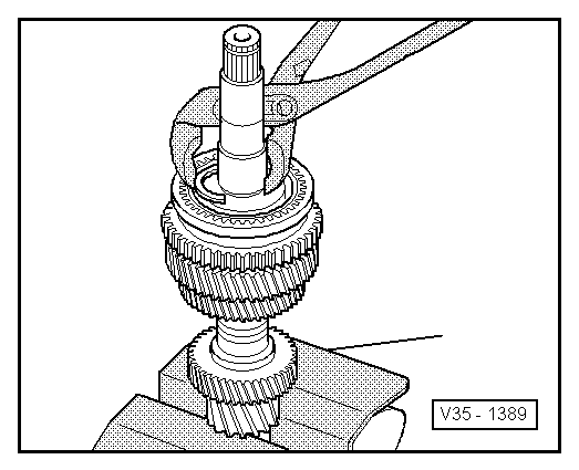
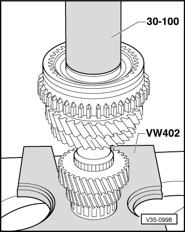
→ Fig.2     Pressing off 1st gear sliding wheel with sleeve -1-, thrust washer -2-, taper roller inner/outer race -3-

 
V35-1388

→ Fig.3     Pressing circlip out of groove

Warning!
Prevent uncontrolled springing of circlip. Danger of accident!
 
V35-1002

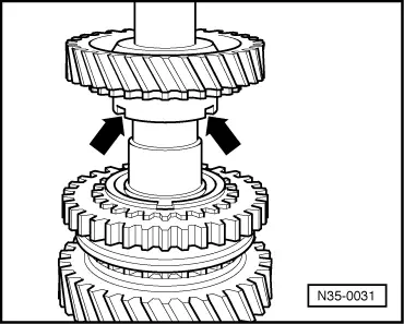
→ Fig.4     Pressing off 1st and 2nd gear locking collar and synchro-hub

After removing securing ring press 2nd selector gear and locking collar/synchro-hub off together.

 
V35-1158

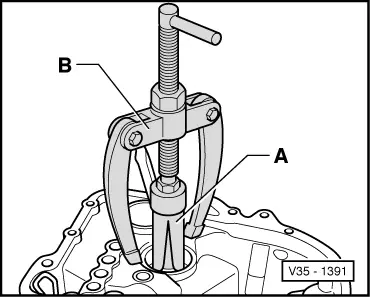
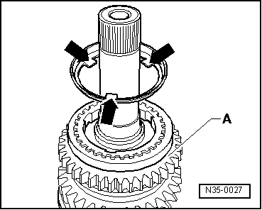
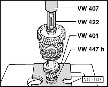
→ Fig.5     Pulling off small taper roller bearing inner race

A - Vice clamps/vice

  • ‒ Fit gripping device and tension behind bearing rollers, then turn bearing and retension gripping device.
 
V35-1390

→ Fig.6     Pressing on taper roller bearing inner race

 
V35-1391

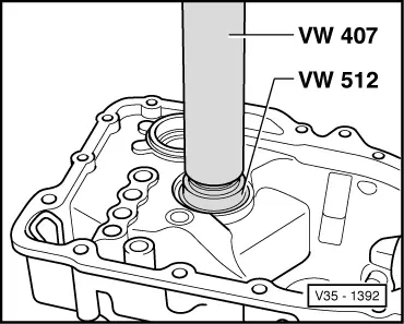
→ Fig.7     Pulling taper roller bearing outer race out of clutch housing

A - Internal extractor, e.g. Kukko 21/6, 37 ... 46 mm

B - Counter support, e.g. Kukko 22/2

 
V35-1392

→ Fig.8     Pressing in taper roller bearing outer race

 
V35-1389

→ Fig.9     Inserting circlip

 
V35-1138

→ Fig.10     Checking 1st and 2nd gear inner-ring for wear

  • ‒ Press inner ring onto 2nd selector gear cone and measure gap "a" with a feeler gauge.

Gap "a"

New dimension

Wear limit

1st and 2nd gear

0.75 ... 1.25 mm

0.3 mm

 
V35-1137

→ Fig.11     Checking 1st and 2nd gear synchro-ring for wear

  • ‒ Press synchro-ring, outer-ring and inner-ring onto selector gear cone and measure gap "a" with feeler gauge.

Gap "a"

New dimension

Wear limit

1st and 2nd gear

1.2 ... 1.8 mm

0.5 mm

 
N35-0029

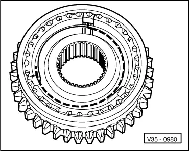
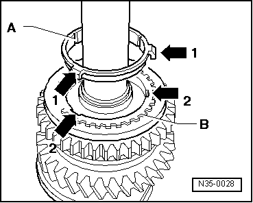
→ Fig.12     Installation position of outer-ring, inner ring and 2nd gear synchro-ring

  • ‒ Place inner ring -A- on 2nd selector gear.

The angled lugs (arrow 1) point towards outer ring -B-.

  • ‒ Fit outer ring -B-.

The lugs (arrow 2) engage in the selector gear recesses (arrow 3).

  • ‒ Fit synchro-ring -C-.

The grooves (arrow 4) engage in the inner ring -A- lugs (arrow 1).

 
N35-0030

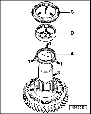
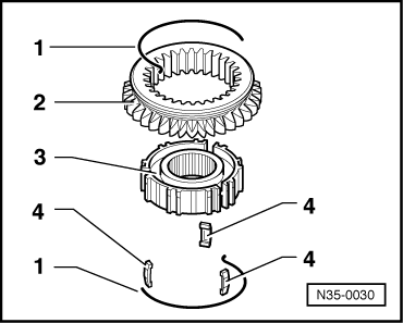
→ Fig.13     Dismantling and assembling 1st and 2nd gear synchro-hub and locking collar

  •      1 -     Spring
  •      2 -     Locking collar
  •      3 -     Synchro-hub
  •      4 -     Locking piece
  • ‒ Slide locking collar over synchro-hub.

The small recesses for locking pieces in synchro-hub and locking collar must align with one another.

 
V35-0980

→ Fig.14     Assembling 1st and 2nd gear locking collar/synchro-hub

The locking collar has been pushed over the synchro-hub.

  • ‒ Insert locking pieces into small recesses and install springs 120° off-set. The angled end of the spring must locate in the hollow locking piece.
 
V35-0998

→ Fig.15     Pressing on locking collar/synchro-hub

Installation position:

Locking collar groove for selector fork towards 1st gear, the teeth for reverse gear towards 2nd gear.

Turn synchro ring so that the grooves align with the locking pieces.

 
N35-0027

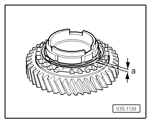
→ Fig.16     Installation position for 1st gear outer-ring

The lugs (arrows) face towards reverse gear -A-.

 
N35-0028

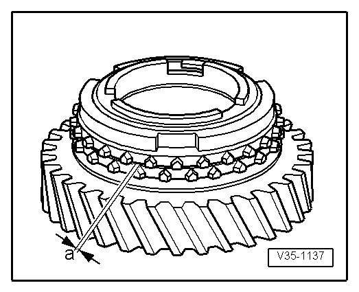
→ Fig.17     Installation position synchro-ring -A- 1st gear (inner ring)

The lugs (arrow 1) locate in the recesses (arrow 2) in the synchro-ring -B-.

 
N35-0031

→ Fig.18     Installation position 1st selector gear

The recesses in the shoulder (arrows) locate in the lugs of the outer-ring (arrows => Fig.16 )

 
V35-1387

→ Fig.19     Pressing on taper roller bearing inner race

Adjusting output shaft > < Adjusting input shaft