volkswagen Workshop Repair Guides

Volkswagen Workshop Service and Repair Manuals

Adjusting input shaft > < Adjusting selector finger and selector sleeve
5-speed manual gearbox 085
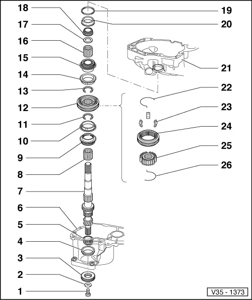
Dismantling and assembling input shaft
 
V35-1373

Notes:

  • ◆ When installing new gears, consult technical data
    .
  • ◆ If the position of the taper roller bearings is affected when exchanging parts, the input shaft must be re-adjusted. See adjustment overview
  • Torx socket head bolt M 8,
    40 Nm
    • ◆ Fitted piece on bolt head locates dished spring.
  • Dished washer
  • 5th gear
    • ◆ Removing and installing
      => Page 34-73
 
V35-1373
  • Taper roller bearing outer race
    • ◆ Pressing out => Fig.1
    • ◆ Pressing in => Fig.2
  • Taper roller bearing inner race
    • ◆ Pulling off => Fig.3
    • ◆ Pressing on => Fig.4
  • Gearbox housing
  • Input shaft
    • ◆ Adjusting => Page 35-13
  • Needle roller bearing
    • ◆ Lubricate before inserting
  • Selector gear for 3rd gear
    • ◆ Pressed off with locking collar/3rd and 4th gear synchro-hub => Fig.8 and pressed on => Fig.13
 
V35-1373
  • 3rd gear synchro-ring
    • ◆ Checking for wear
      => Fig.10
  • Circlip
    • ◆ Pressing out => Fig.7
    • ◆ Inserting => Fig.9
  • Locking collar with 3rd and 4th gear synchro-hub
    • ◆ Parts are paired
    • ◆ Pressing off => Fig.8
    • ◆ Assembling => Fig.11 and Fig.12
    • ◆ Pressing on => Fig.13
  • Circlip
    • ◆ Pressing out => Fig.7
    • ◆ Inserting => Fig.9
  • 4th gear synchro-ring
    • ◆ Checking for wear
      => Fig.10
 
V35-1373
  • Selector gear for 4th gear
  • Needle roller bearing
    • ◆ Lubricate before inserting
  • Thrust washer
  • Taper roller bearing inner race
    • ◆ Can be removed without using tools
  • Shim
    • ◆ Determining thickness => Page 35-13
  • Taper roller bearing outer race
    • ◆ Pulling out => Fig.5
    • ◆ Pressing in => Fig.6
  • Clutch housing
  • Spring
    • ◆ Installation position => Fig.12
 
V35-1373
  • Locking pieces (Qty. 3)
  • Locking collar
  • Synchro-hub
  • Spring
    • ◆ Installation position => Fig.12
 
V35-1374

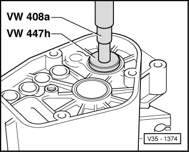
→ Fig.1     Pressing out taper roller bearing outer race

 
V35-1375

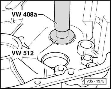
→ Fig.2     Pressing in taper roller bearing outer race

 
V35-1376

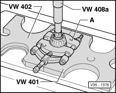
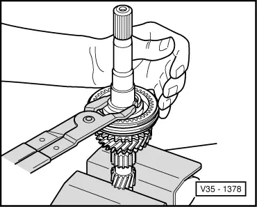
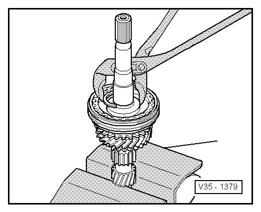
→ Fig.3     Pulling off small taper roller bearing inner race

A - Separating device 22 ... 115 mm, e.g. Kukko 17/2

 
V35-1377

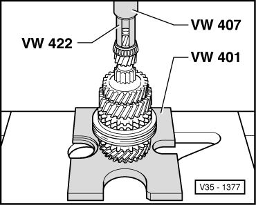
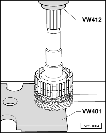
→ Fig.4     Pressing on small taper roller bearing inner race

 
V35-1381

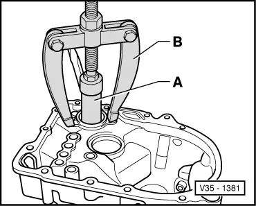
→ Fig.5     Pulling out taper roller bearing outer race

A - Internal extractor 37 ... 46 mm, e.g. Kukko 21/6

B - Counter support, e.g. Kukko 22/2

 
V35-1382

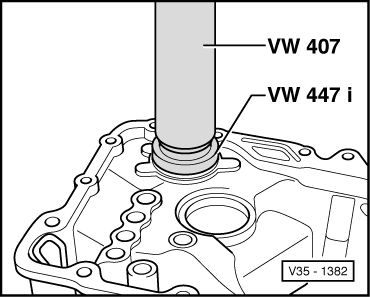
→ Fig.6     Pressing in taper roller bearing outer race

 
V35-1378

→ Fig.7     Pressing circlip out of groove

Warning!
Prevent uncontrolled springing of circlip. Danger of accident!
 
V35-1004

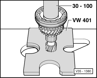
→ Fig.8     Pressing off synchro-hub

  • ‒ After removing securing ring press off synchro-hub and 3rd selector gear.
 
V35-1379

→ Fig.9     Inserting circlip

 
V35-0975

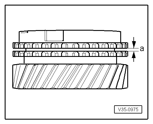
→ Fig.10     Checking synchro-ring for wear

  • ‒ Press synchro-ring onto the gear cone and measure gap "a" with feeler gauge.

Gap "a"

New dimension

Wear limit

3rd and 4th gear

1.1 ... 1.7 mm

0.5 mm

 
V34-0671

→ Fig.11     Assembling locking collar and synchro-hub for 3rd and 4th gear

Installation position:

Short splines below circumferal groove (lower arrow) face 3rd gear.

Groove on end face (upper arrow) face 4th gear.

 
V35-0981

→ Fig.12     Locking collar/synchro-hub assembled

  • ● Locking collar is pushed over synchro-hub.
  • ‒ Insert locking pieces and install springs 120° off-set. The angled end of the spring must locate in the hollow locking piece.
 
V35-1380

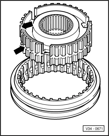
→ Fig.13     Pressing on 3rd and 4th gear synchro-hub with locking collar

Adjusting input shaft > < Adjusting selector finger and selector sleeve