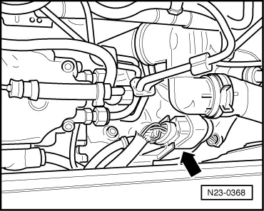
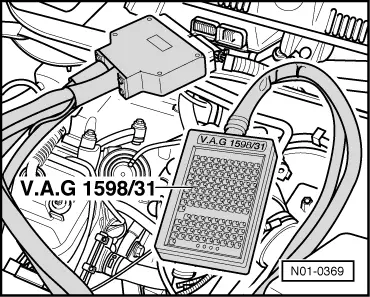
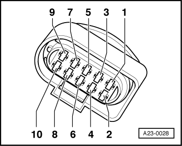
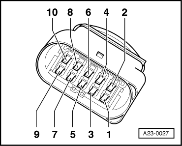
volkswagen Workshop Repair Guides

Volkswagen Workshop Service and Repair Manuals

Checking intake manifold flap change-over > < Checking needle lift sender G80
Checking injection timing device control range
Checking the injection timing device control range is carried out in function 04 (Basic settings). Using this procedure the commencement of injection valve -N108- is pulsed so that the extremity values for advanced (early) and retarded (late) positions for the injection timing device can be read in display zone 3 of measured value block 4.
Special tools and workshop equipment required
t  Hand multimeter -V.A.G 1526C- or multimeter -V.A.G 1715-
t  Fault reader -V.A.G 1551- or vehicle system tester -V.A.G 1552- with diagnosis cable -V.A.G 1551/3-
t  Adapter set -V.A.G 1594C-
t  Adapter cable, 121-pin -V.A.G 1598/31-
t  Current flow diagram
Test procedure
–  Connect fault reader -V.A.G 1551- or vehicle system tester -V.A.G 1552- and select engine electronics control unit with “address word 01”. Engine must be idling.
   
Indicated on display:
–  Press keys 0 and 4 for function “Initiate basic settings” and confirm entry with Q key.
 
Rapid data transfer                 HELP
Select function XX                    
Indicated on display:
–  Press keys 0, 0 and 4 for “Display group number 4” and confirm entry with Q key.
 
Basic setting                        
Input display group number XXX       
Indicated on display:
Specification in display zone 3: Advanced 7.0...9.0° BTDC
After approx. 10 seconds the timing device is moved to the retarded (late) position.
 
System in basic setting 4            ->
900 rpm    advanced     7.9° BTDC      66%
Indicated on display:
Specification in display zone 3: Retarded 3.0...5.0° BTDC
–  Press key.
–  Press keys 0 and 6 for function “End output” and confirm entry with Q key.
–  Switch off ignition.
If the specifications are not attained:
–  Check commencement of injection valve -N108- as follows:
 
System in basic setting 4            ->
900 rpm    retarded     3.9° BTDC      74%
–  Disconnect 10-pin connector for commencement of injection valve -N108- (connector to injection pump quantity adjuster).
  N23-0368
–  Measure resistance between connector contacts 9+10.
Specification: 12.0…20.0 Ω
If the specification is not achieved:
–  Renew commencement of injection valve -N108- → Item.
–  Read fault memory, if necessary, repair any faults and then clear fault memory → Chapter, Reading and clearing fault memory.
If the specification is attained:
  A23-0027
–  Connect adapter cable, 121-pin -V.A.G 1598/31- to control unit wiring harness. The engine control unit remains disconnected.
  N01-0369
–  Check lines between adapter cable, 121-pin -V.A.G 1598/31- and 10-pin connector for open circuit according to current flow diagram. Contact 9 + socket 114 Contact 10 + socket 1 Contact 10 + socket 2.
Cable resistance: max. 1.5 Ω.
–  Also check wiring for short to one another, short to vehicle earth and short to battery positive.
Specification: ∞ Ω.
If no fault in lines is detected:
–  Renew engine control unit → Chapter.
  A23-0028

Checking intake manifold flap change-over > < Checking needle lift sender G80