
940 L4-2.3L SOHC VIN 88 B230F (1992)
Locate the 2-pin connector. Start at the alarm control module and follow the cable harness to the 2-pin connector under the dashboard.
A2
CHECKING THE STARTER INHIBITOR SWITCH MODE/YEAR 1992
Check that the pink cable from the alarm control module is connected at position 3 on the 4-pin connector.
Check that the blue-green cable from the alarm control module is spliced to the blue-green cable from the starter motor.
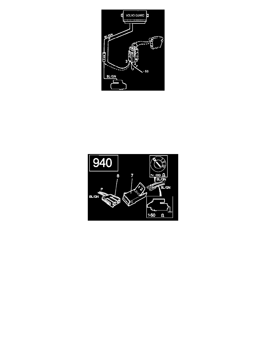
940 1993-94
Use an ohmmeter between one of the two blue-green cables and ground.
The blue-green cable which joins the pink cable in the connector should give a reading of (infinite resistance) between the cable and ground.
The blue-green cable which joins the blue-green cable should give a reading of 1-50 between the cable and ground.
If both values are correct, continue to A4. If the readings are not within the range, continue to A3.
960 1993-94