
940 L4-2.3L SOHC VIN 88 B230F (1992)
Reading: approx. 0 ohm
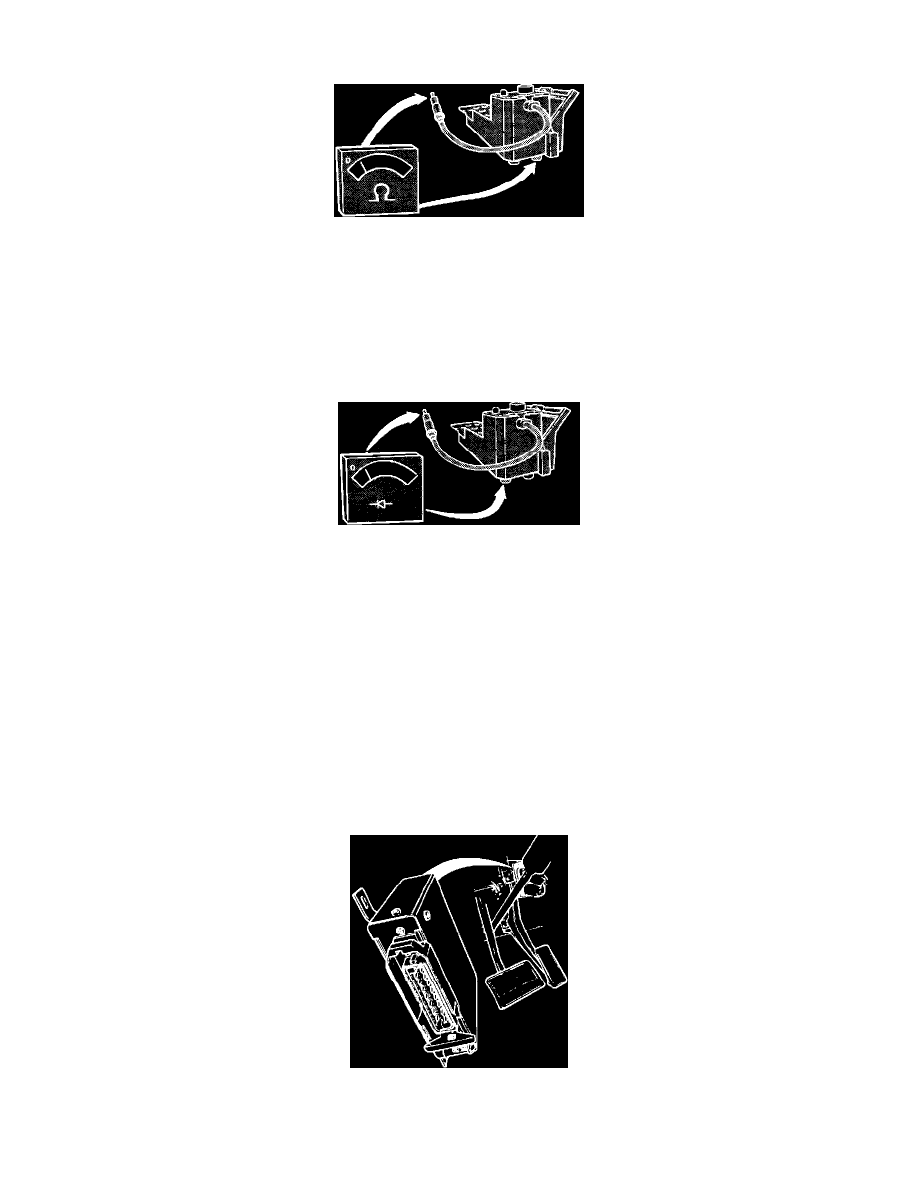
Checking Diagnostic Socket Wire
17.
Connect the ohmmeter between selector cable and pin #8 (selector button) under diagnostic socket.
a. Reading: infinite
b. When the button is depressed;
Reading: 0 ohm
Checking Diagnostic Socket Diode
18.
Connect a diode tester between the diagnostic socket diode and the selector wire. Tester red (+) lead connects under diode, black (-) lead connects
to the selector wire.
19.
If a reading is obtained, diode is operating correctly.
20.
If diagnostic socket fails any test between step 13 and 16, check wiring and connectors. Replace as needed.
21.
If the socket fails test 17 to 19, replace diagnostic socket and retest.
22.
Disconnect the test equipment. Remove the #1 fuse and reconnect the ECU and all other connectors, install the kick panel and glove compartment.
Ensure that the rubber seal in the ECU connector is installed before it is connected to the unit.
23.
Reinstall the #1 fuse.
Ignition
TESTING PROCEDURE:
NOTE: While trouble shooting, always check the wiring, fuses and connectors for good condition and routing. Use the wiring diagrams found in
CHASSIS ELECTRICAL DIAGRAMS to supplement your testing efforts.
Accessing Ignition ECU Connector
1.
Turn ignition OFF.