
940 L4-2.3L SOHC VIN 88 B230F (1992)
Checking Ground Connections
11.
Connect an ohmmeter between pin 5 and ground.
Reading: 0 ohm
12.
If not, check wiring and fix as necessary.
13.
Then connect the ohmmeter between pin 17 and ground.
Reading: 0 ohm
14.
If not, check wiring and fix as necessary.
15.
Then connect the ohmmeter between pin 19 and ground.
Reading: 0 ohm
16.
If not, check wiring and fix as necessary.
17.
Then connect the ohmmeter between pin 29 and ground.
Reading: 0 ohm
18.
If not, check wiring and fix as necessary.
19.
Disconnect the test equipment. Remove the #1 fuse and reconnect the ECU and all other connectors, install the kick panel and glove compartment.
Ensure that the rubber seal in the ECU connector is installed before it is connected to the unit.
20.
Reinstall the #1 fuse.
Ignition
TESTING PROCEDURE:
NOTE: While trouble shooting, always check the wiring, fuses and connectors for good condition and routing. Use the wiring diagrams found in
CHASSIS ELECTRICAL DIAGRAMS to supplement your testing efforts.
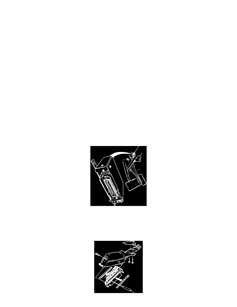
Accessing Ignition ECU Connector
1.
Turn ignition OFF.
2.
Access ignition ECU by removing the panel under left hand side of instrument panel.
3.
Remove ECU connector by pushing out the catch and folding out the wire cluster.
4.
Check ignition ECU ground connections at intake manifold. They should make good contact.