
940 L4-2.3L SOHC VIN 88 B230F (1992)
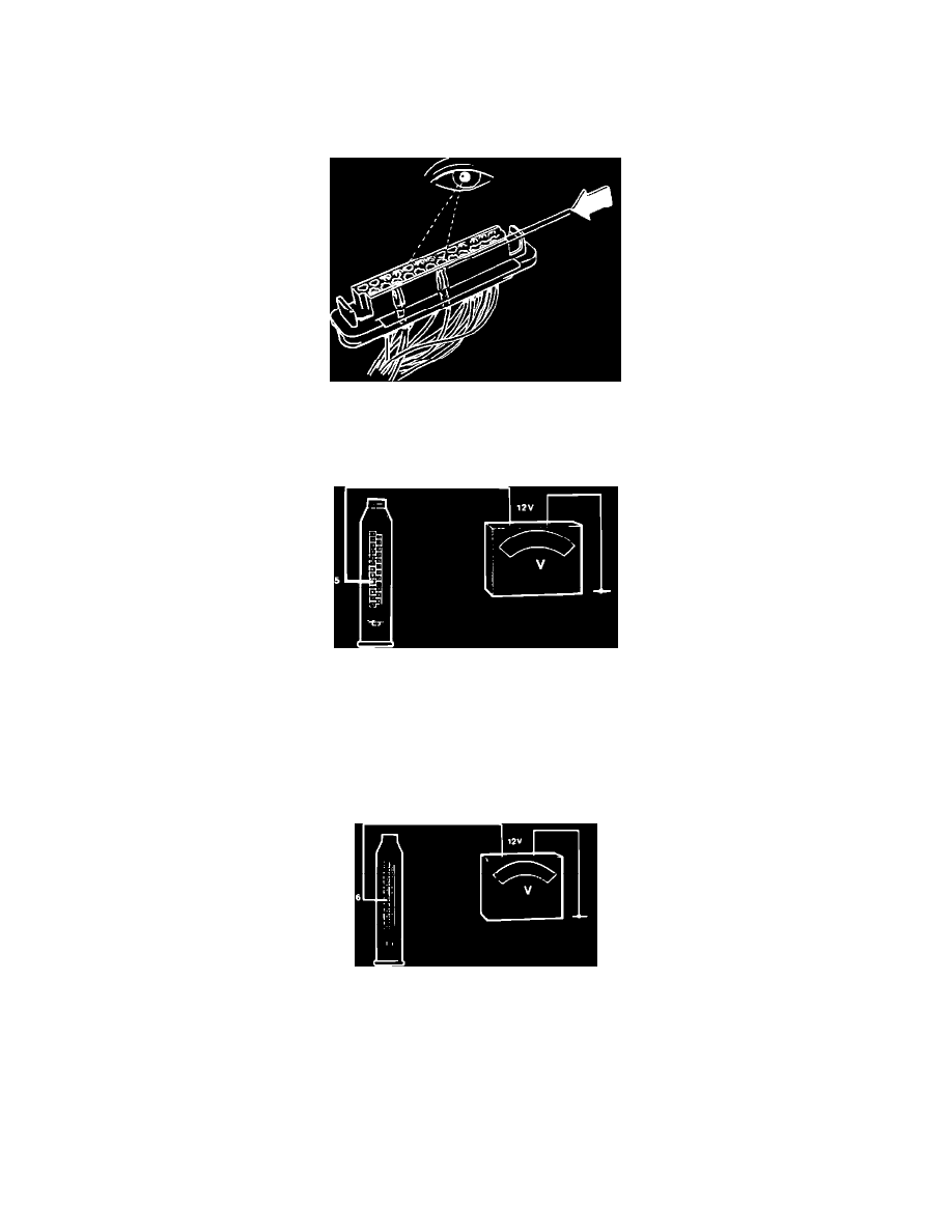
Removing Protective Cover
5.
Remove connector protective sleeve.
IMPORTANT:^ Never check connections from the front. Connectors can get damaged and worsen the problem.
^ Check connections through the holes in the connector.
^ Connection pin numbers are printed on the connector side.
Checking Terminal Pins
6.
Check that terminal contacts have been pushed down evenly in connector.
7.
If any connectors have been pushed down to far, poor connection may result.
Checking Battery Supply
8.
Check main power supply by connecting a voltmeter between pin 5 (brown) in ECU connector and ground.
Reading: approx. 12 volts
9.
If no voltage registers, check wire between ECU and fuse-box located behind the center console ash tray. Check fuse #1, #3 and wiring to battery
(incl. battery terminals). Repair as necessary.
Checking Pin 6
10.
Turn ignition ON.
11.
Connect a voltmeter between pin 6 (blue) at ECU connector and ground (checking ignition switch).
Reading: approx. 12 volts
12.
If not, check wiring and connectors. If no fault found, replace ignition switch and retest.
13.
Turn ignition OFF.