
940 L4-2.3L SOHC VIN 88 B230F (1992)
Procedure
Commence by recording any fault codes stored in the fuel and ignition system diagnostic memory.
Remove/disconnect:
-
battery ground lead
-
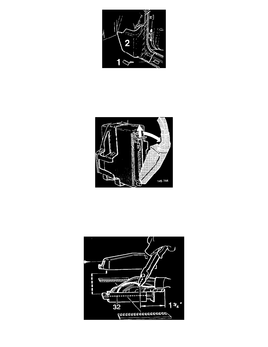
front screw in sill protector (1)
-
cover over fuel system control unit (2)
Important!
The control unit power supply must be disconnected when removing or installing the unit, otherwise the unit may suffer damage.
Disconnect 35-pin connector from control unit.
Cut tie securing rubber protector and fold aside protector.
Remove protective cover from connector.
Modify 35-pin connector as follows: