
940 L4-2.3L SOHC VIN 88 B230F (1992)
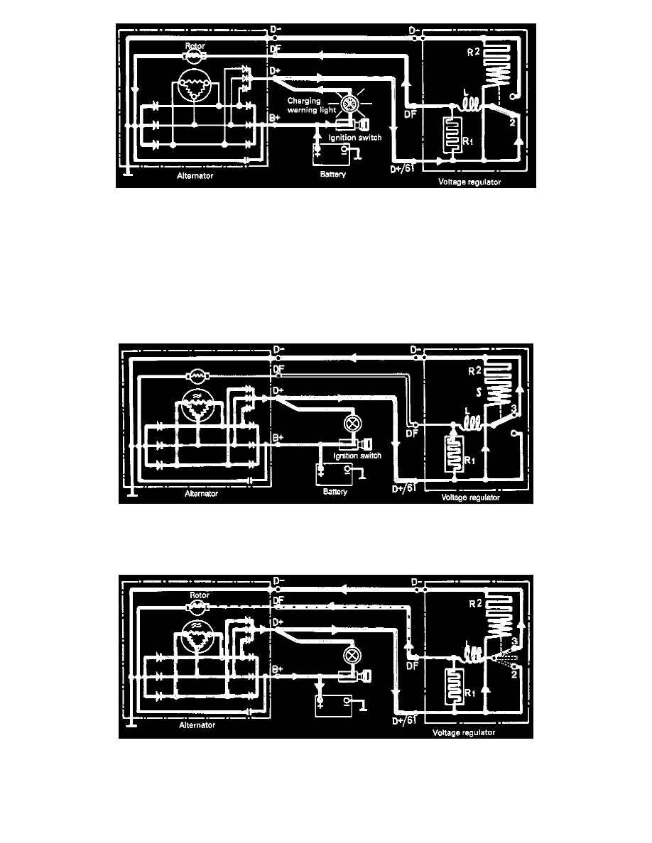
Ignition on, engine not running
A small current flows through the ignition switch, charging warning light and voltage regulator to the car's earth through the rotor winding. This small
current is the source of the magnetic field in the rotor that is necessary to initiate charging by the alternator.
Function
The voltage regulator does not operate when the engine is not running. The current passes through the lower contact (2) and the reactive coil (L) in the
voltage regulator to the rotor.
Engine running, upper control range regulation
When the voltage approaches its upper control voltage the armature in S is drawn to its upper position and D+/61 current is connected via the upper
contact (3). The rotor consequently receives no current and the alternator voltage drops.
Working principles
The cycle of operations below is repeated very quickly when the regulator is in operation. Lower control range position (2) = rotor receives
(max) exciter current. Upper control range position (3) = rotor receives no exciter current. Intermediate position = current flows through resistance R1
giving a mean exciter current. This means that the current is continuously regulated.
Temperature compension