
940 L4-2.3L SOHC VIN 88 B230F (1992)
16.
Using a suitable punch, remove needle bearing from inside of housing. Bearing should only be removed if it requires replacement.
17.
Remove lock rings, thrust washers and piston from rack. Fill lock ring grooves with grease and slide tube away from rack teeth.
18.
Using tool No. 1819, remove inner tube seal and narrow brass bushing.
19.
Remove O-ring and washer from spacer tube.
20.
Remove star washer, bearings and seal from right side housing.
21.
Remove seal and O-ring from pinion housing cover.
22.
Remove O-ring and depressor from pre-tension piston.
23.
Remove rings from pinion valve unit.
ASSEMBLY
1.
Clean all parts and inspect for wear and damage, replace as necessary. Valve housing should not be disassembled. Replace if defective.
2.
Lubricate needle bearing using suitable lubricant. Using a suitable drift, install needle bearing. Bearing bottom should be flush with housing. If
bearing is set too far, pinion preload will be affected.
3.
Install lower washers and thrust bearing.
4.
Install pinion assembly, roller bearing and pinion housing cover.
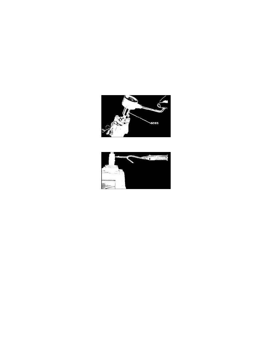
Fig. 5 Checking Pinion Torque. 240 Series w/power Steering (ZF Gear Use Tool No. 5179)
Fig. 7 Checking Bearing Preload (typical)
5.
Adjust pinion using one of the following methods:
a. Using adapter No. 5179 and torque wrench, check torque of pinion, Fig. 5. Torque should be 1.3-2.2 inch lbs.
b. Using suitable spring gauge, check pinion torque, Fig. 7. Scale should read 3.7-6.5 lbs.
c. Preload is adjusted by altering the bearing washer under the cover. Washers are available in various sizes.
6.
Remove pinion assembly, bearings and spacers.
7.
Install all rings on valve body grooves.
8.
Install seal and spacer ring in pinion housing.
9.
Install bronze bushing in spacer tube, chamfered side down.
10.
Install spacer tube seal in spacer tube.
11.
Install O-ring and washer on spacer tube.
12.
Install seal, bearings and star washer in right side housing.
13.
Fill lock ring grooves and coat surrounding area with suitable grease, then slide spacer tube into steering rack from smooth end and pass it quickly
over lock ring grooves.
14.
Install piston, thrust washers and lock ring on rack.
15.
Install center tube locking collars and lock rings. Also apply a suitable lubricant on collar threads and lock rings.
16.
Place right side housing in a vise and using tool No. 5178 attached to a torque wrench, install center tube on right side housing. Torque retaining
collar to specifications. Ensure scribe marks made previously are aligned.
17.
Install rack and spacer tube as a unit in pinion housing.
18.
Using tool No. 5178 attached to a torque wrench, install center tube to pinion housing. Torque retaining collar to specifications. Ensure scribe
marks made previously are aligned.
19.
Punch a mark in aluminum housing at one of the recesses on each housing to lock retaining collars.
20.
Install pre-tensioning piston, without O-ring, in housing.
21.
Set up pre-tension measuring fixture No. 5865 using one cover bolt hole fitted with a 45mm X 8mm bolt. Assemble tool with pre-tension spring
between bolt head and tool.
22.
Move gear from lock to lock and ensure it does not bind or jam.
23.
Using a suitable micrometer, measure distance between housing face and piston top, checking measurement at three different points of steering
rack. Subtract .004-.006 inch from smallest reading obtained and select a washer of the approximate thickness. Washers are available in thickness