
940 L4-2.3L SOHC VIN 88 B230F (1992)
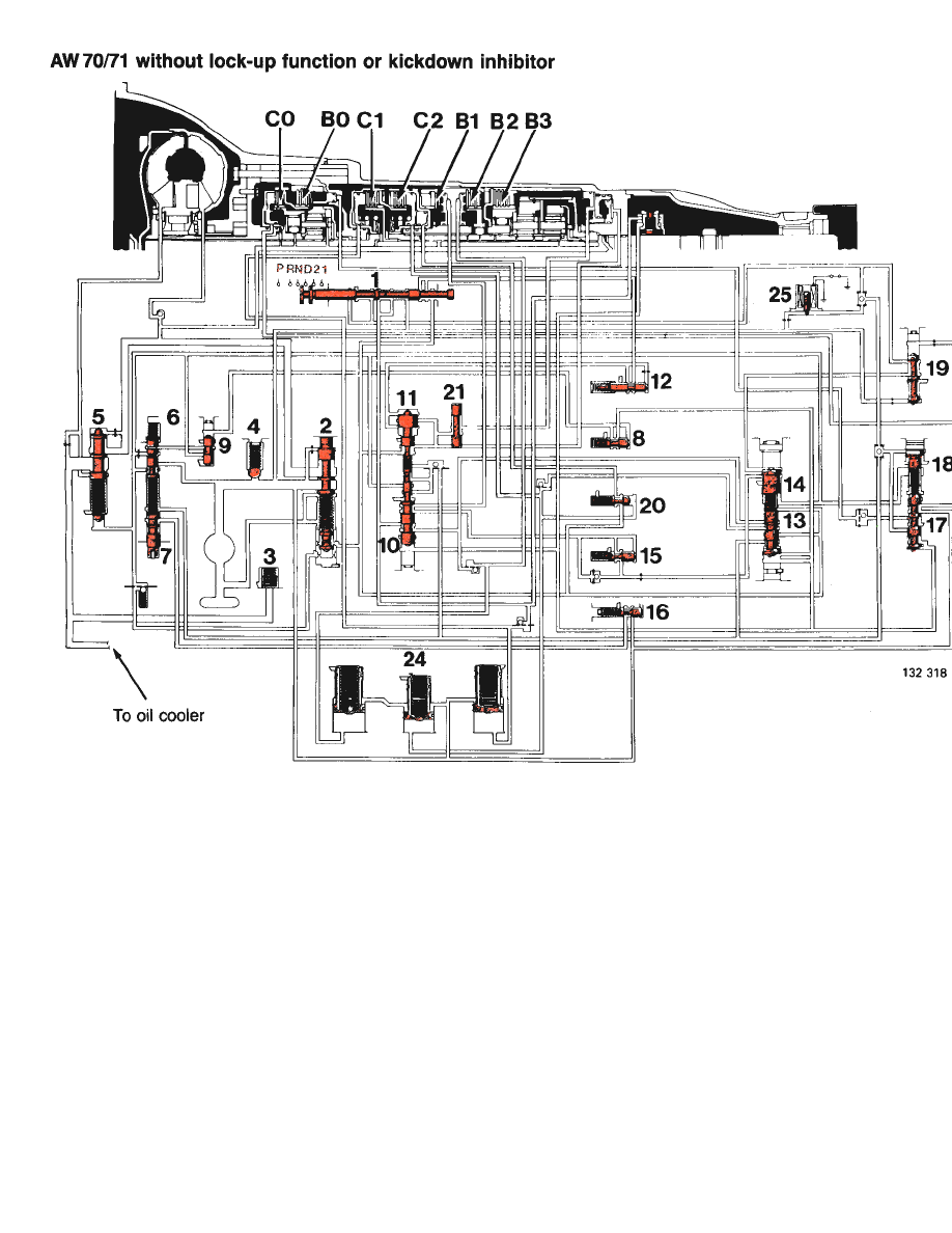
AW70/71 without lock-up function or kickdown inhibitor.
Modulator Valve, Manual 3-2 (15)
The valve reduces the operating pressure to brake B1 for gentler engine braking in 2nd gear.
Detent Regulator Valve (16)
Located upstream of the kickdown valve, the detent regulator valve is supplied continuously with line pressure. In this position, it reduces the
line pressure to a suitable circuit pressure which is then used by the kickdown valve to control the shift valves and downshift valve 4-3.
Shift Valve 3-4 (17)
Throttle pressure (which varies with throttle opening) is supplied to one end of the valve and an opposing governor pressure (which varies with
the speed of the car) to the other.
Line pressure is supplied to clutch C0 and brake B0 through two ports in the middle of the valve, the position of the valve (or, in effect, the
balance between the governor and throttle pressures) determining which is pressurized.
Downshift Valve, Manual 4-3 (18)
The valve is either operated manually by the switch on the gear selector lever or automatically by the kickdown function.
Under these conditions, the valve is supplied with system pressure or kickdown pressure, as appropriate, at one end.
In manual operation (by means of the solenoid valve), the downshift valve moves shift valve 3-4 to its bottom position (i.e. 4th gear is