
43 Transmission (Construction): General Information
- Make
- Volvo
- Model
- 900 Series 960 Factory Service Manual
- Year
- 1991–1997
- Section
- 43 Transmission › General Information › Construction
Construction
M 46 Transmission
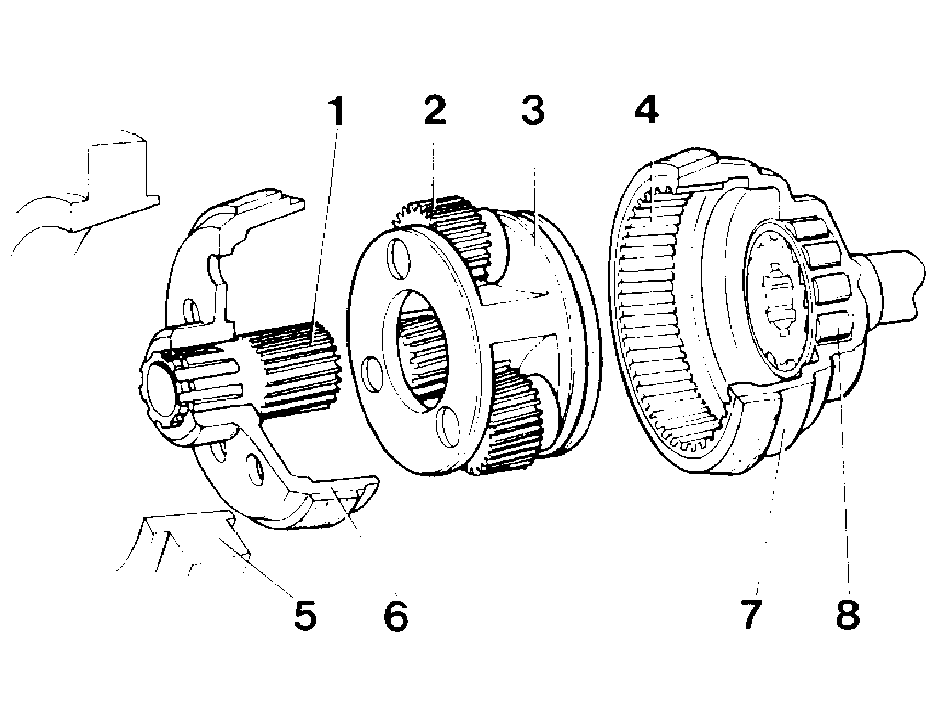
- 1. Sun gear
- 2. Planetary gear
- 3. Planetary gear carrier
- 4. Ring gear
- 5. Brake drum attached to gear case
- 6. Combined brake and clutch sliding member (cone clutch)
- 7. Output drum
- 8. One way clutch
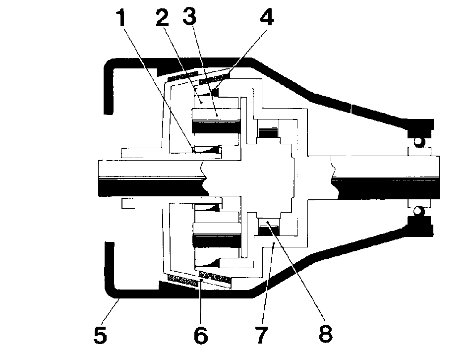
Main components of the overdrive are a planetary gear, hydraulic-controlled clutch and a one way clutch. The lower part of the overdrive casing also contains a hydraulic circuit for operating the cone clutch and keeping the moving parts sufficiently lubricated.
The cone clutch (6) can slide along the input shaft. In direct drive the gear train is locked to the output shaft. In overdrive the clutch is in contact with the gear case and the planetary carrier rotates.
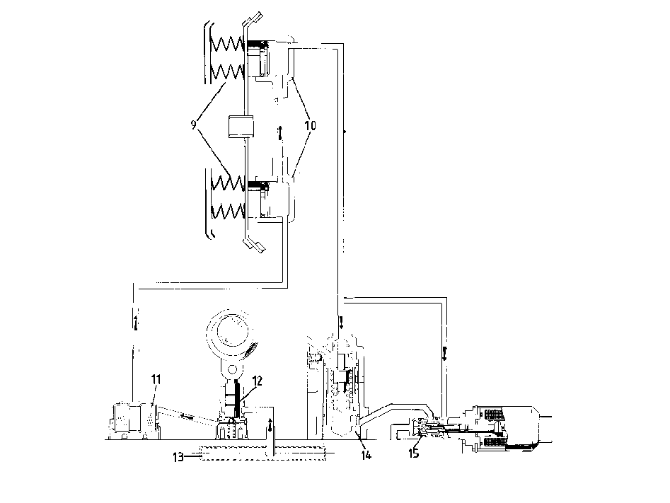
- 9. Thrust springs (4x)
- 10. Operating pistons (2x)
- 11. Oil strainer
- 12. Oil pump
- 13. Sump with suction filter
- 14. Relief valve
- 15. Solenoid valve
Four springs (9) load the cone clutch in one direction, and two operating pistons, under hydraulic pressure, are used to move the clutch in the opposite direction.
Oil pump (12)
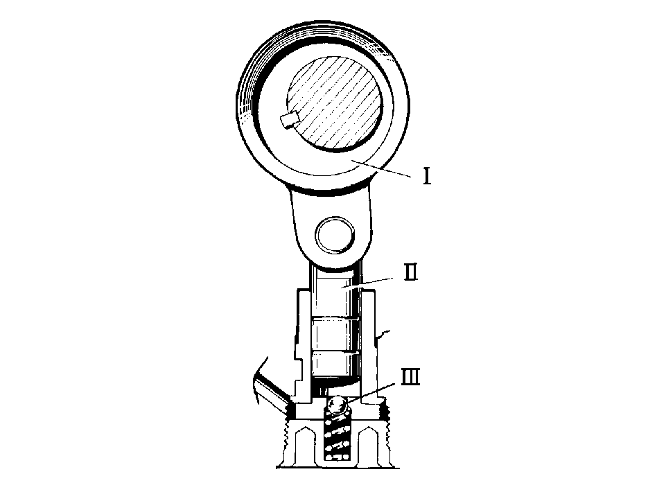
Oil pump drive is effected by an eccentric (1) mounted on the input shaft. It drives a plunger which draws oil from the sump through a suction filter (13) and strainer (11) and delivers it to the operating pistons (10).
A non-return valve (3) closes the pump outlet during the suction stroke.
On leaving the operating pistons the oil is conducted to the solenoid valve (15) and relief valve (14).
Relief valve (14)
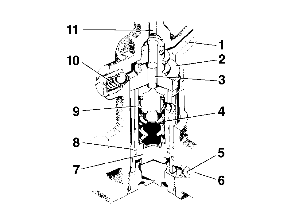
- 1. Tube-mainshaft
- 2. Valve seat
- 3. Relief valve (A)
- 4. Spring
- 5. Control orifice
- 6. Tube solenoid valve
- 7. Plunger (B)
- 8. Cylinder
- 9. Spring
- 10. Relief valve (lubricating oil pressure)
- 11. Tube-oil pump
The relief valve has 3 separate functions. (1) it maintains a residual pressure within the system in direct drive, (2) it maintains a high pressure when the overdrive is engaged and (3) it ensures smooth overdrive engagement and disengagement under varying conditions.
The small piston (A) is the relief valve. The larger piston (B) is affected by oil pressure and operates via two springs on the small piston. These springs provide a gradual pressure increase and thereby a smooth engagement of the overdrive. The outer spring also controls the pressure in direct drive.
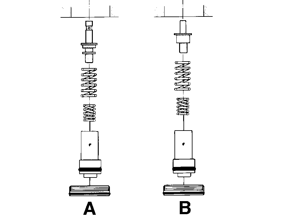
- A. New type
- B. Early type
Two types of relief valves (A) have been used throughout the years. New type valves are the longer of the two and operate at a slightly higher pressure. Also, oil pressure variations are kept at a minimum and there is less risk of slipping especially when the transmission is hot.
Lubricating system
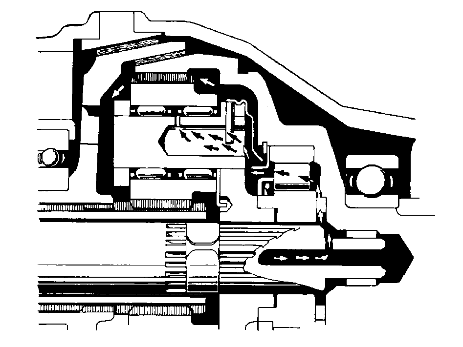
Oil passes the relief valve (small piston) and flows through a passage to the overdrive main shaft. A passage from the main shaft leads the oil to the one way clutch and the shaft bushing.
A baffle catches the oil which then flows via the planetary gear to the transmission housing.
A separate relief valve in the passage from the oil pump provides an even lubricating oil pressure.
Solenoid valve (15)
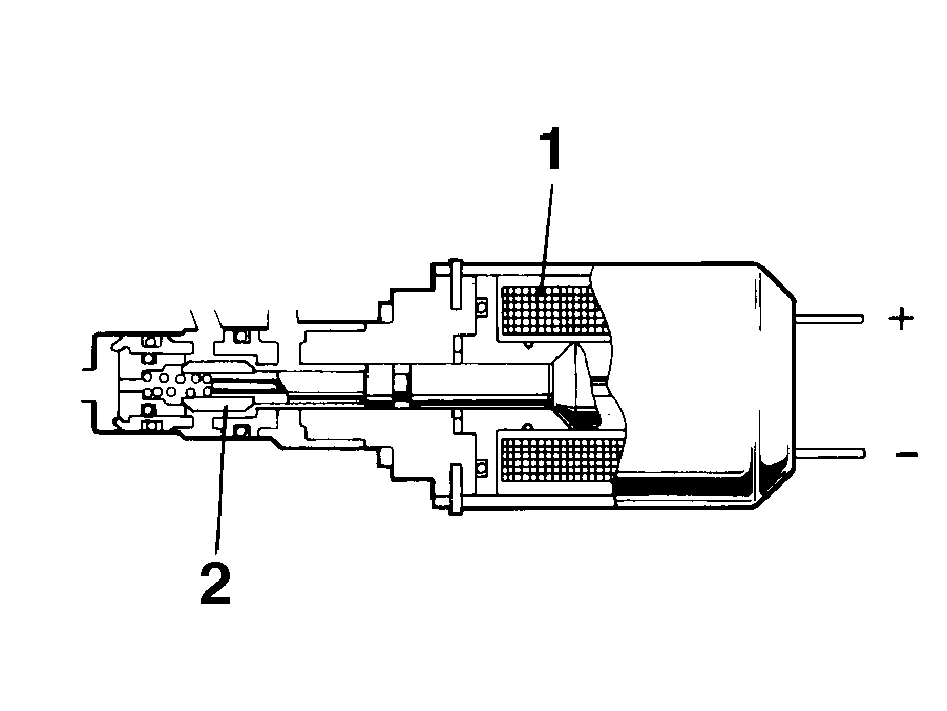
- 1. Electromagnet
- 2. Solenoid valve
Contains an electromagnet which is actuated when electric current is turned on or off.
Electrical system
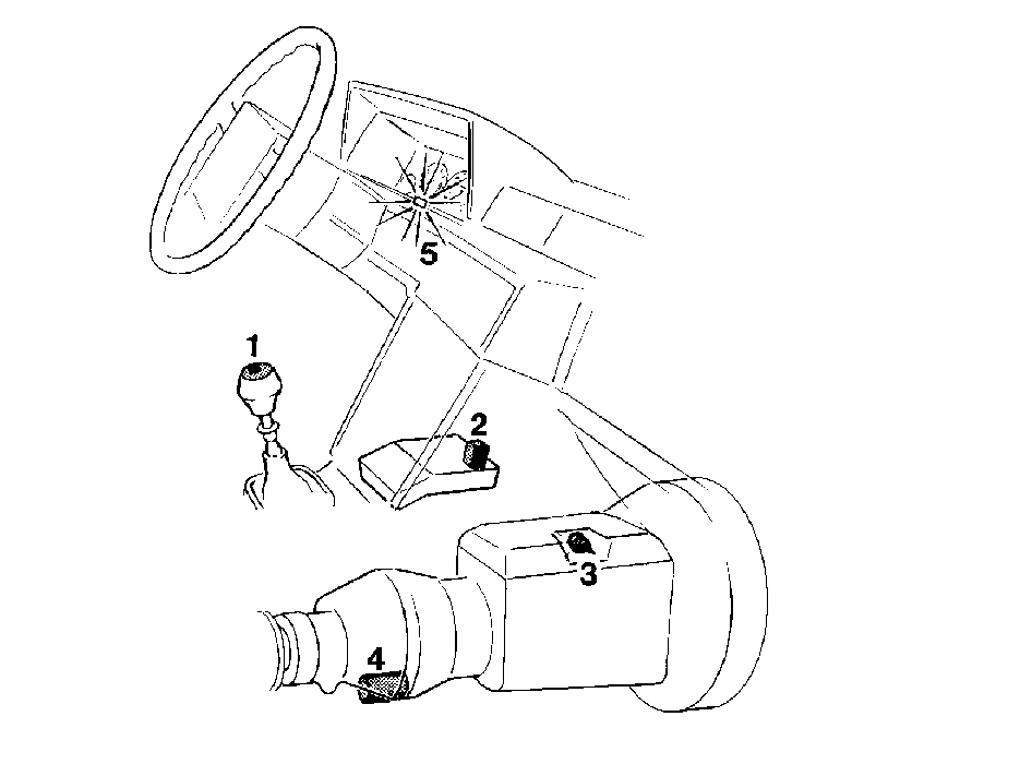
Electrical system consists of:
- 1. Push button on gear lever (54)
- 2. On/off relay in central electrical unit (123)
- 3. Transmission switch (77)
- 4. Overdrive solenoid (201)
- 5. Indicator lamp (OD) (112)
(Figures in parenthesis refer to components illustrated in wiring diagrams.)
Overdrive wiring diagram
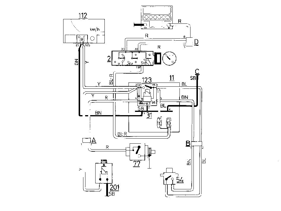
- 1 Battery
- 2 Ignition switch
- 11 Control electrical unit
- 54 Push button switch
- 77 Transmission switch
- 112 Indicator lamp
- 123 On/off relay
- 201 Solenoid valve
Parts & tools for this job For 1991 Volvo 900 Series
- TOOLTorque wrenchSearch: 3/8 inch torque wrench
- TOOLSocket setSearch: socket set metric
- BOOKHaynes manualSearch: Haynes manual Volvo 900 Series
Links open Amazon search results in a new tab. As an Amazon Associate I earn from qualifying purchases.