
Overdrive, replacement
- Make
- Volvo
- Model
- 900 Series 960 Factory Service Manual
- Year
- 1991–1997
- Section
- 43 Transmission › Overhaul instructions › Overdrive, replacement
Overdrive, replacement
Special tools: 999 2834, 999 2836, 999 2709, 999 5244
New overdrive is a mix of type J and P
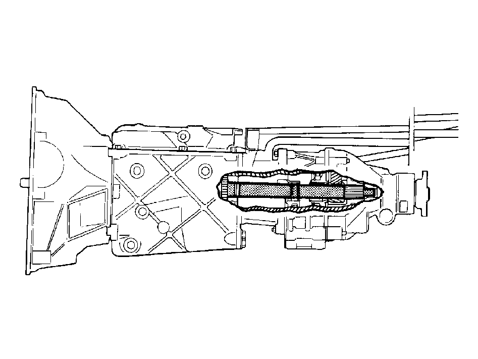
The overdrive of type J has been taken out of production and has been replaced by a new J/P-combination with a larger center hole.
The change is a consequence of introducing the larger main shaft in the M46-transmissions from 1987
The larger main shaft is also used in gasoline turbo models from 1986 that has overdrive of the P-type.
NOTE: Overdrives of type J can only be used in combination with the smaller main shaft.
Overdrives of the mixed type J/P can only be used in combination with transmissions with the larger main shaft. Otherwise the planet gears will not receive lubricated.
Part number for the overdrive of mixed type J/P 1208516-3.
The new overdrive is used on model year 1987 with engines B230E and B230F
New hydraulic pistons in overdrives of type J, J/P and P
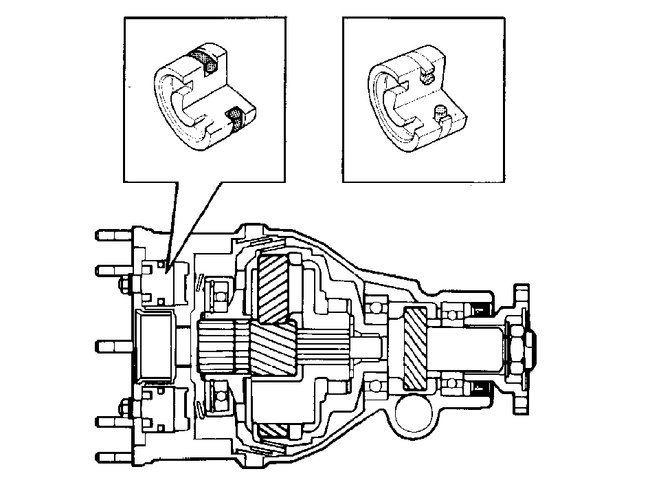
Hydraulic pistons with improved seals were introduced successively in overdrives of type J, J/P and P during 1988.
The new seal consists of a heavy-duty O-ring that replaces the existing O-ring and the seal ring made of Teflon. The seal is of a type that lasts longer, which reduces the risk of leakage.
The change takes place from and including the part and serial number.
| PART NUMBER | Serial number | |
|---|---|---|
| Type P | 1 208 605 | 6787 |
| Type P | 1 208 606 | 1273 |
| Type P | 1 208 607 | 6446 |
| Type J/P | 1 208 608 | 9821 |
| Type P | 1 208 628 | 870 |
| Type J/P | 1 208 639 | 60 |
| Type J/P | 1 208 650 | 1 |
Overhauling
When overhauling overdrives of type J and J/P with hydraulic pistons of the earlier type, where the Teflon rings are worn out, the pistons shall be replaced with the new type (part number 6 814 454-2) with the new O-ring seal (part number 6 814 455-9). (See instructions below).
NOTE: If slipping takes place during engagement or disengagement, or when reversing, the clutch discs shall be replaced or a service kit shall be installed.
Clutch disc 3 502 761-4 shall be installed when slipping occurs. This applies to overdrives with the part numbers noted above.
The service kit (part number 261 183-6) shall be installed to correct defects on overdrives that do not have the above part numbers. The overdrive mechanism and the clutch (that is, reducer valve springs and return springs) must be pressure-adapted. These are included in the service kit.
Replacing hydraulic pistons
Remove the overdrive (see L1-L2 (Unloading)).
Tool 2709
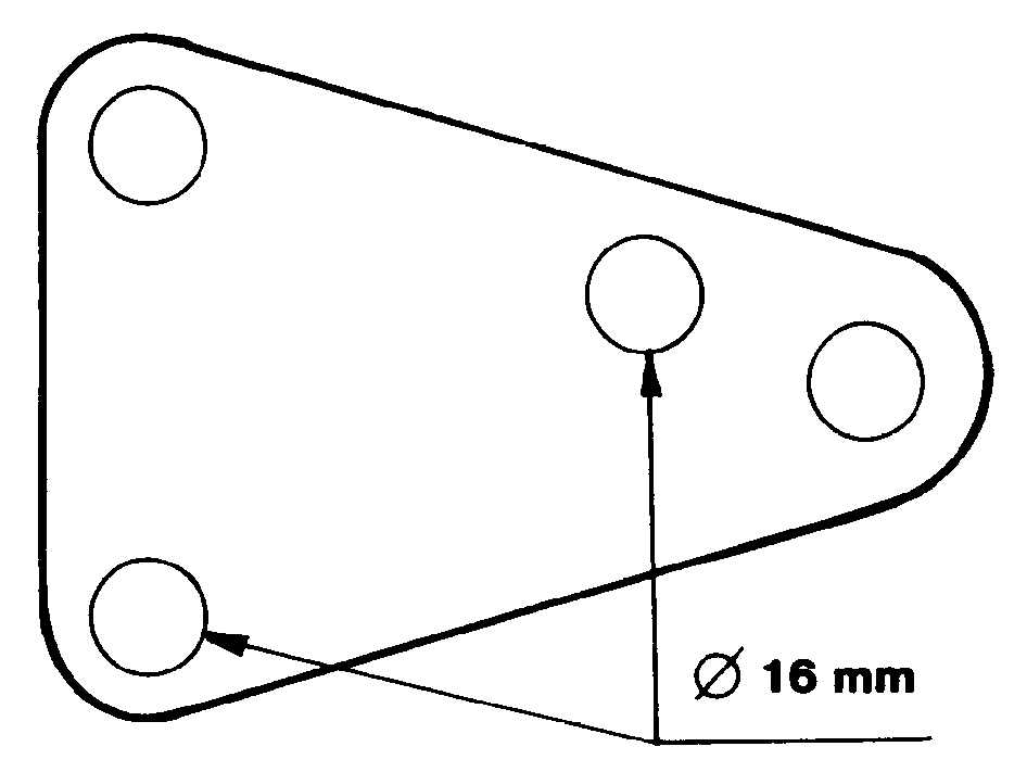
If tool 999 2709 has to be used on a drive flange with three pins, it must be changed as follows:
Drill the two indicated holes to 16 mm.
Remove:
gasket
Pressure plates
Remove the hydraulic pistons
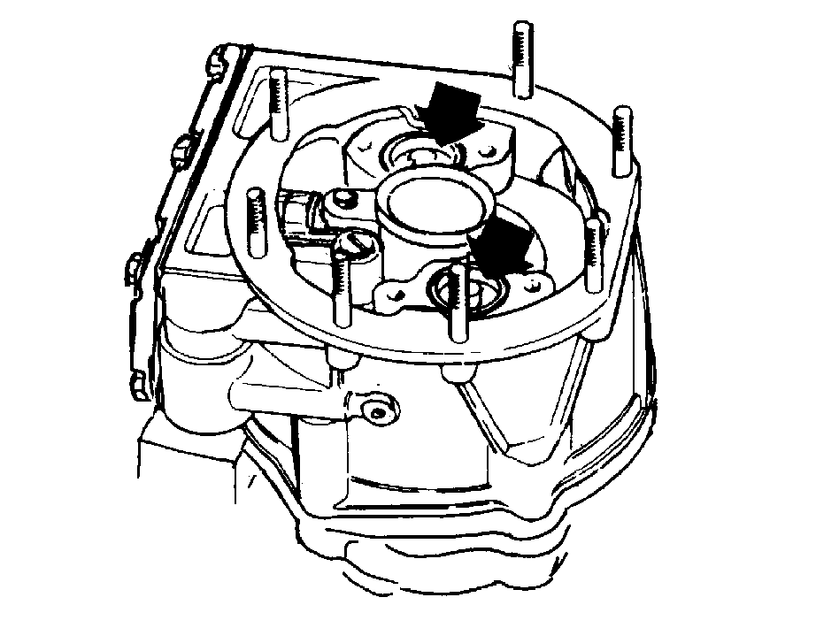
Use pliers when removing
Install:
- New hydraulic pistons and O-rings
- Pressure plates, with new nuts
Tighten the nuts crosswise with 10 Nm (1.0 kpm).
Install the overdrive (see Installation ).
Replacing clutch discs/installing service kit
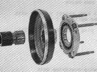
Remove the overdrive (see L1 ).
Tool 2709
If tool 999 2709 has to be used on a drive flange with three pins, it must be changed as follows:
Dismantle the overdrive
Dismantle the clutch unit
Remove the lock rings and pull out sun gears and the clutch disc from the bearing carrier.
Replace the clutch disc
Lubricate the facing on the new clutch disc with ATF-oil, type F or G.
Assemble the clutch unit
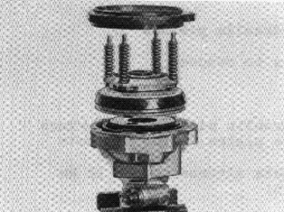
Install:
- the clutch unit
- springs (new springs if the service kit is used)
- gasket between the rear housing and the brake drum, so that the gasket ends up in correct position
- brake drum
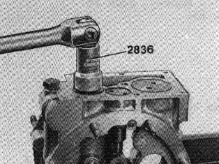
Replacing reducer valve springs (when installing service kit)
Remove the oil sump and primary filter
Remove the reducer valve's plug
Use plug wrench 999 2836. Tap on the plug with a plastic mallet to facilitate the work.
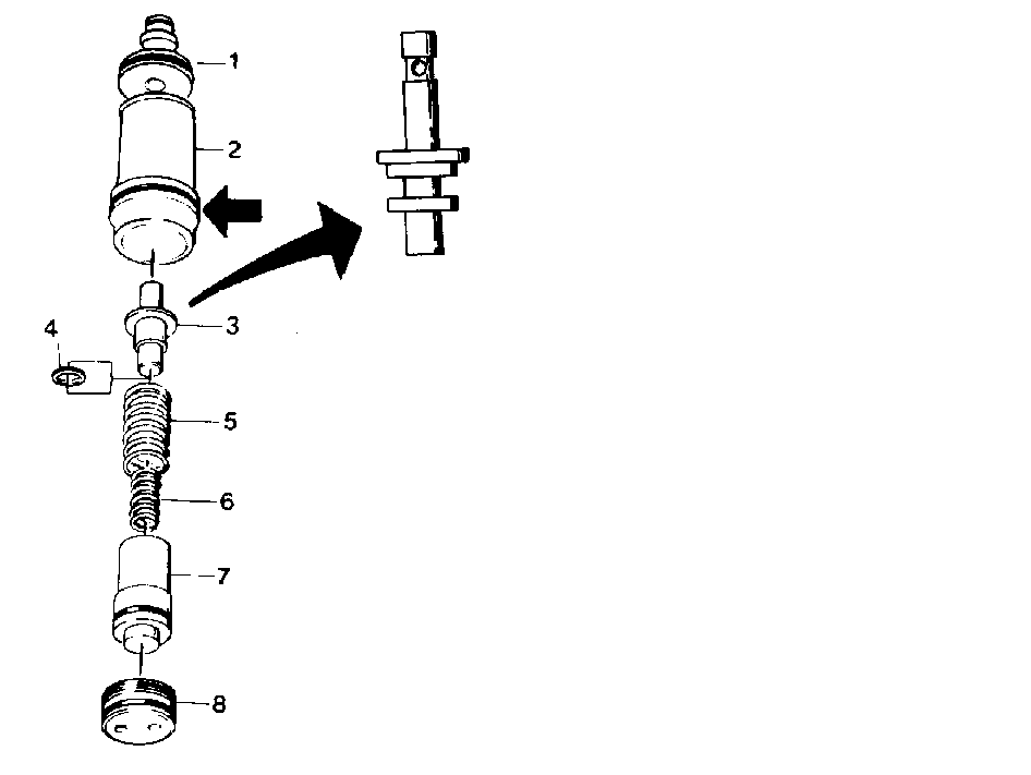
Remove the reducer valve and the components
Remove all adjusting washers
Install new valve
(Install the latest version with new, internal spring 6.)
Tighten the plug with 22 Nm (2.2 kpm).
Install the overdrive
See work steps L1-L3 Unloading.
Install the overdrive
See work step L3 Installation
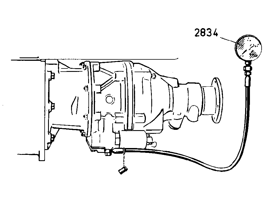
Connect the oil pressure gauge 2834
Remove the plug under the solenoid valve and connect oil pressure gauge 999 2834. Run the engine when the car is lifted and supported.
Read off the pressure when the car runs in high gear (direct gear) at approx. 70 km/h (44 mph). The value shall be approx. 0.15 MPa (21.8 lb/in2 ).
Engage overdrive and read off the pressure.
Correct values:
| Gasoline-powered turbo D 24 TIC and D 24 T with asbestos-free friction discs | 2.8-3.1 MPa(405-450 Ib/in2) |
| Other types | 2.7-2.9 MPa (390-420 Ib/in2) |
Unloading
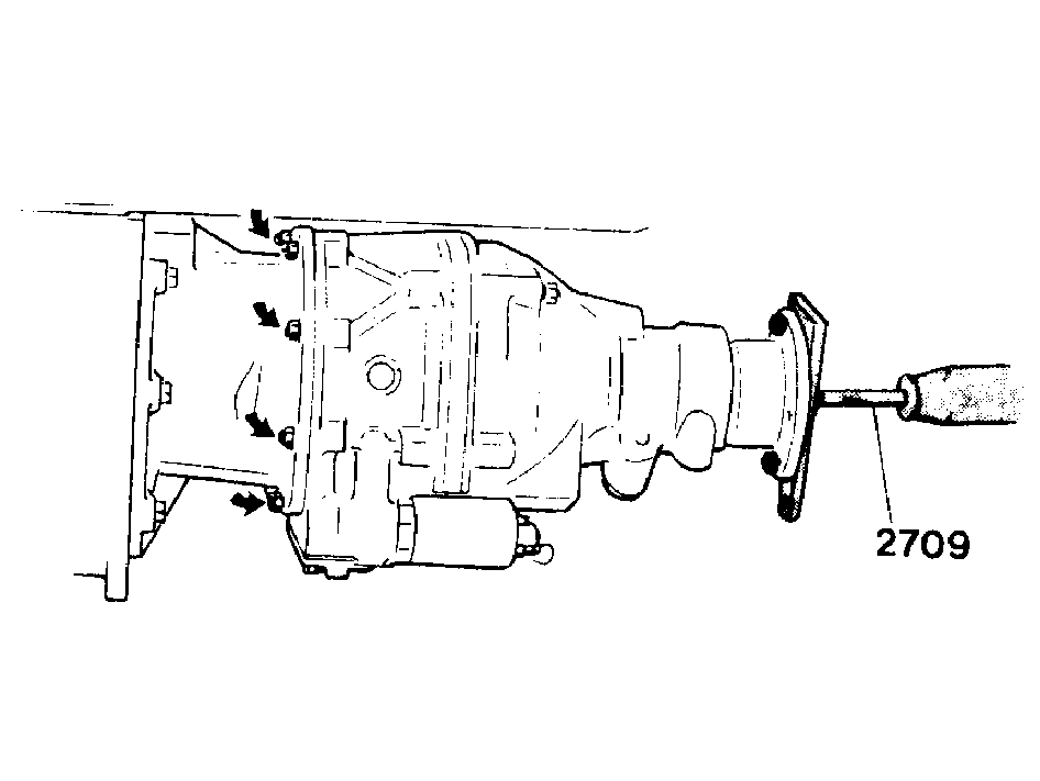
To facilitate removal, the car should first be driven with overdrive engaged, then the overdrive is disengaged with the clutch pedal pressed down. The latter is important to avoid torsional stresses in the shaft between the plane carrier and the free-wheel (on the condition that the overdrive works). Any stresses disappear even if the oil with 2.0-2.5 MPa (20-25 kp/cm2) pressure is connected to the outlet at the control valve. With this pressure connected, the overdrive is engaged and disengaged.
Removal
Remove the propeller shaft from the drive flange with tool 999 5244. (999 5244 is not needed for rubber joint.)
Remove the transmission's cross member and lower the transmission.
NOTE: On engine types B 200/230, check that the distributor does not strike the firewall.
Disconnect the cables to the control solenoid.
Loosen the screws that hold the overdrive to the transmission. Pull the overdrive unit straight back until it releases from the transmission's main shaft. Use extractor 999 2709 if the overdrive is stuck.
NOTE: If the overdrive cannot be released in the above manner: Remove the drive flange and carefully tap loose the rear housing. Then remove the overdrive from the rear, part by part.
Installation
Move up the overdrive on the transmission's output shaft and tighten the nuts.
Install the transmission member
Connect the cables to the control solenoid.
Plug in the connector for the monitoring function of the torque limiter.
Install the propeller shaft.
Fill oil.
Test-drive the overdrive with the rear wheels off the ground.
Check the oil level.
Parts & tools for this job For 1991 Volvo 900 Series
- TOOLTorque wrenchSearch: 3/8 inch torque wrench
- TOOLSocket setSearch: socket set metric
- BOOKHaynes manualSearch: Haynes manual Volvo 900 Series
Links open Amazon search results in a new tab. As an Amazon Associate I earn from qualifying purchases.