
Engine – Function
- Make
- Volvo
- Model
- C70 Factory Service Manual
- Year
- 2006–2013
- Section
- 09 Miscellaneous › Design and Function › Engine – Function
Engine – Function
Oil pan
The main task of the oil pan is to be the reservoir for the oil. It is also part of the cylinder block. There are a number of components which are secured in or on the oil pan.
The oil level is checked via the dipstick which is connected to the oil pan. A suction pipe with a nozzle supplies the oil pump with oil which is then pumped onwards in the engine. To facilitate the suction function of the oil pump, there is a bleed valve which ensures that any air in the system is evacuated. The oil flows through the oil cooler to lower its temperature. The oil cooler is screwed to the outside of the oil pan.
Crankshaft
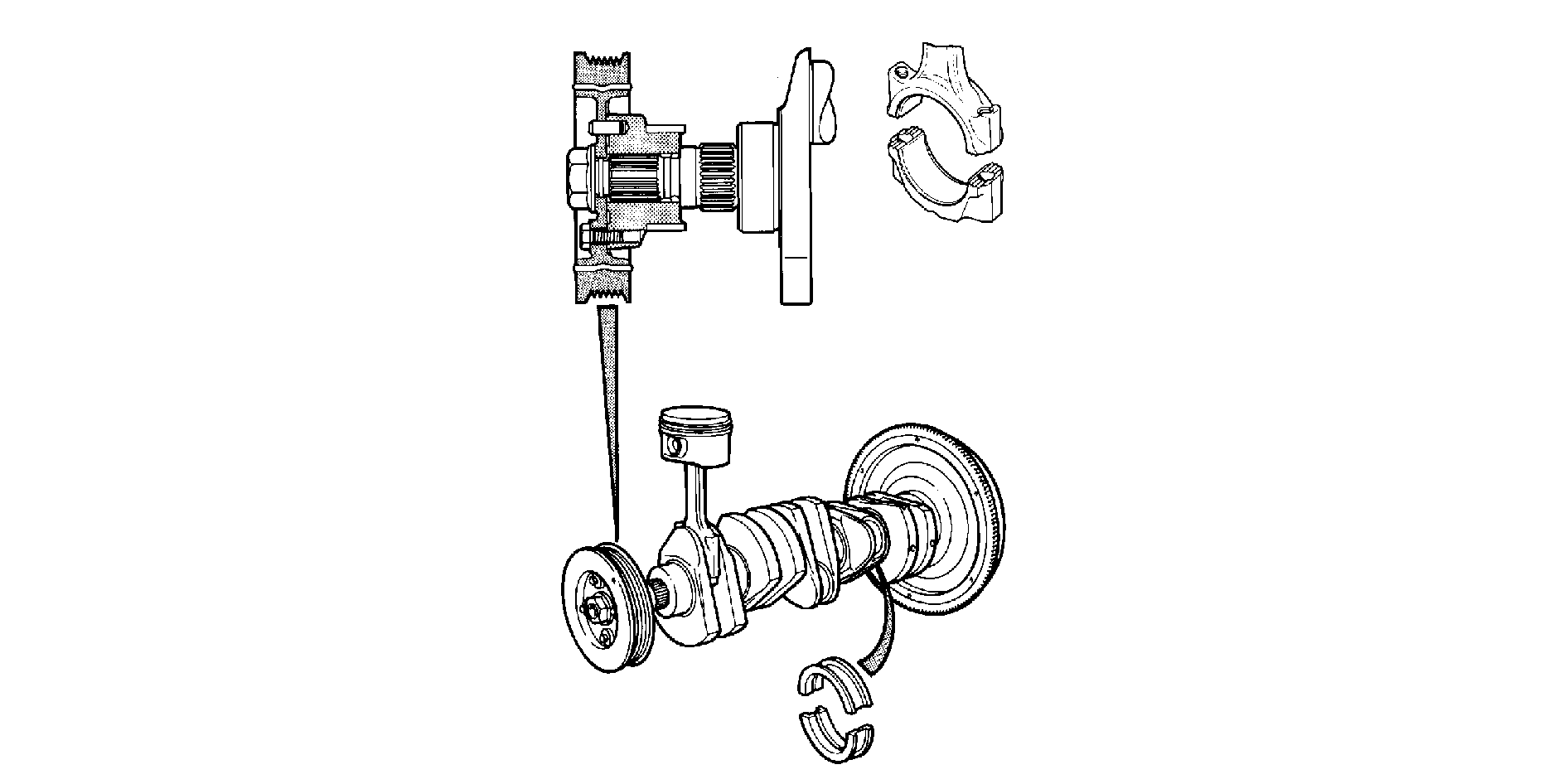
The function of the crankshaft is to transfer the upwards and downwards power of the piston movement. The engine is pendulum mounted, which provides better crankshaft balance than a non-pendulum mounted engine. The connecting rod, which is secured on the crankshaft, transfers the upwards and downwards movement of the piston into crankshaft rotation.
Piston
The main task of the piston is to compress the fuel/air mixture during the different strokes. The piston rings provide a seal so that the fuel/air mixture is not forced past the piston. The uppermost ring expands when the piston moves downwards. The second ring, as well as sealing is an oil scraper ring during the downward piston movement. The third ring ensures that the oil is drained via the drainage hole.
Camshafts, valve system
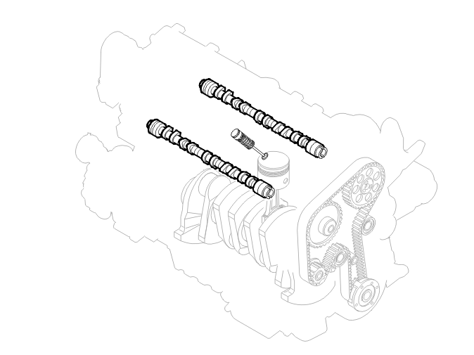
The camshafts and valves let in the fuel/air mixture for the ignition stage. The camshafts and valves then release the fuel/air mixture after ignition.
Conical valve springs allow smaller shims to be used and reduce the total moving mass. The valve springs operate progressively. This means that there is little force at the beginning and the end of the closing phase, but considerable force during maximum valve lift.
The camshaft is rotated by the timing belt which is turned by the crankshaft. When the cam lobes on the camshaft press in the valve lifter, the valve is also pressed in and lets the fuel/air mixture out. A VVT unit on the camshaft can vary the valve timing steplessly using the oil pressure. The function of the VVT unit is to determine when to open or close the valves (within specific tolerances).
Mechanical belt tensioner

The belt tensioner must maintain constant pressure on the timing belt and prevent the belt from jumping off the cogs.
Lubrication system
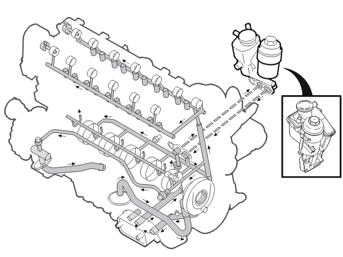
The oil is led from the oil pan via a suction piece to the oil pump. The oil pump is located on the cylinder block. The oil is then pumped onwards to the oil cooling system and then to the oil filter.
The oil flows from the filter through a cast oil duct in the intermediate section to the main bearings. The oil then flows through bored channels in the crankshaft to the connecting rod bearings. The camshafts are supplied with oil by a bored channel in the cylinder block. The channel runs through the cylinder head, where it flows out at the bottom of the upper half of the cylinder head. There is a cross duct in the channel to the cylinder head which carries oil to the pistons via a piston cooling valve. The oil flows on via an oil duct to the bearing for the left-hand camshaft and the valve lifters (intake side).
The bearings for the right-hand side camshaft (exhaust side) are supplied by a cast cross duct at the front edge of the upper half. This cast cross duct also supplies pressurized oil to the solenoids for the VVT unit. Drain holes in the cylinder block release the oil from the cylinder head and crankshaft bearing back to the oil pan.
Oil filter
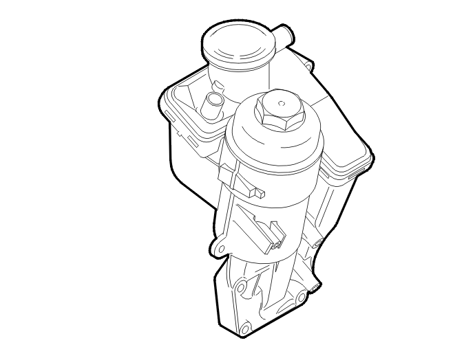
The filter is an environment filter which filters out any dirt particles from the oil. The oil flow from the outside into the filter. If the filter becomes blocked, the by-pass valve opens so that the oil can pass the filter. This ensures that the engine is always lubricated with oil.
Piston cooling valve

The piston cooling valve regulates the oil flow by letting oil through the piston cooling nozzles.
Oil pump
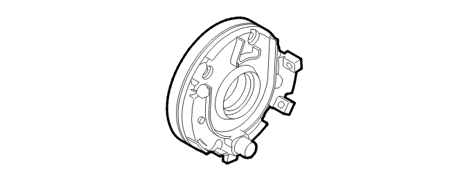
The oil pump pumps oil from the oil pan via channels in the intermediate section and cylinder block into the cylinder head and onwards in the system. The oil pump is on the end of the crankshaft. The crankshaft runs through the oil pump. A duo-centric gear wheel reduces the flow of oil, increasing the pressure. This results in a pulse action which forces out the oil. The oil can only flow in one direction.
Injector
The injector ensures engine performance in certain situations. The fuel comes from the fuel rail to the inlet for the injector and then through the injectors. The fuel is mixed with the intake air. The fuel/air mixture must be as homogenous as possible.
Evaporative emission (EVAP) system
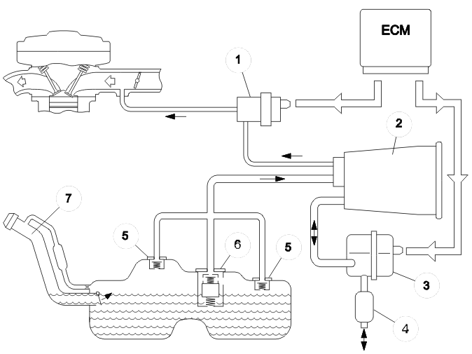
| 1 | evaporative emission system (EVAP) valve | 5 | Roll over valve |
| 2 | EVAP canister | 6 | FLVV (Fill Limit Vent Valve) |
| 3 | Leak diagnostic pump | 7 | Filler pipe with recirculation pipe |
| 4 | Air cleaner (ACL) |
The EVAP canister absorbs the hydro-carbons in the fuel vapors so that they are not released. The engine control module (ECM) controls the EVAP valve. The hydro-carbons are emptied from the EVAP canister when the valve is open. When emptying, the atmospheric air flows through the EVAP canister (where stored hydro-carbons are gathered) and on to the intake manifold and combustion chamber. The energy in the hydro-carbons is then used during the combustion process. So that emissions are not negatively affected, the EVAP valve is pulsed by a pulse width modulation (PWM) signal, the frequency of which is calculated by the engine control module (ECM).
The signals from the heated oxygen sensors (HO2S) are used as a reference. The EVAP valve is closed during the leak diagnostic. The leak diagnostic unit checks the gas and fuel filled sections of the EVAP system. Any leaks in the fluid filled sections cannot be detected. When the pump is not activated, it is open so that the fuel tank and EVAP system can "breathe".
A number of parameters must be met before the EVAP canister can be emptied. For example:
- the engine coolant has reached a certain temperature.
- the fuel/air ratio is within the tolerance zones.
During leak diagnostics, the control module activates the pump and test pressurizes/calibrates the pump against a built-in leak scenario in the pump module. A valve then closes so that the pump motor can create overpressure in the tank and EVAP system. The control module is able to determine the size of the leak in the tank and EVAP system by measuring the power consumption of the pump in these two circumstances. If the current level is too low in relation to the level for the in-built leak scenario, there is leakage in the system. The built-in PTC heater element is used to prevent condensation in damp weather which could disrupt the leak diagnostic.
Intake system
Each cylinder has an intake manifold which comes from a plenum chamber. The injectors are on the lower aluminum intake manifold close to the intake valves. This is so that the fuel mixes as well as possible with the turbulent air. The position of the injectors is optimized to minimize wetting the cylinder walls and therefore emissions. There are ducts in the lower intake manifold for the crankcase gases so that they can reach the combustion chamber.
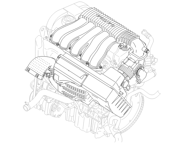
For B5xx4Sx
The air enters via the air intake on the front member. The air is routed via a cold air hose in the air cleaner (ACL) housing. Here there is also a snow valve. This valve opens if the air cleaner (ACL) housing and air intake are blocked by snow. This lets the air flow through and also uses cooling flanges to cool the engine control module (ECM). The air then flows through a funnel with a net which reduces air turbulence before the air reaches the mass air flow (MAF) sensor.
The mass air flow (MAF) sensor controls the mass air flow to the engine. The air then flows to the electrical throttle body (TB) and into the intake manifold. The manifold absolute pressure (MAP) sensor gauges the pressure in the intake manifold. The evaporative emission system (EVAP) valve recirculates the fuel/air mixtures for further combustion. The evaporative emission system (EVAP) valve is by the throttle body (TB). There is a direct terminal from the air cleaner (ACL) to the intake manifold which by-passes the mass air flow (MAF) sensor. There is a brake vacuum ejector in the middle of the hose. The brake vacuum ejector uses the pressure differences in the air cleaner (ACL) housing and plenum chamber to create a flow in the hose to create a vacuum in the brake booster.
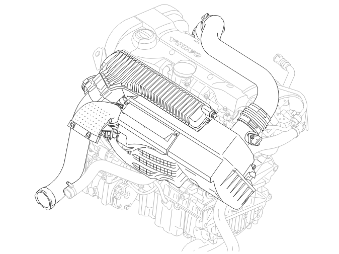
For B5xx4Tx
The air enters via the air intake on the front member. There is a rail in the air intake pipe which divides the pipe to minimize drops in pressure. The air then flows on to the air cleaner (ACL) housing. Here there is also a snow valve. This valve opens if the air cleaner (ACL) housing and air intake are blocked by snow. This lets the air flow through and also uses cooling flanges to cool the engine control module (ECM).
The air then flows through a funnel to the mass air flow (MAF) sensor. The mass air flow (MAF) sensor controls the mass air flow to the engine. The air then flows through a fresh air hose over the engine. The air then passes the turbocharger (TC) and charge air cooler before reaching the electronic throttle body (TB) and being released into the intake manifold. The evaporative emission system (EVAP) valve recirculates the fuel/air mixtures for further combustion. The evaporative emission system (EVAP) valve is by the throttle body (TB).
Throttle body (TB)
The throttle body guides the air flow into the intake manifold. The requested throttle disc angle is obtained by the driver by the accelerator pedal movement / accelerator pedal position. The intake air comes from the air filter housing through the throttle body and on to the intake manifold.
Turbocharger (TC)
The exhaust gases enter the turbine housing via the manifold and then flow out to the exhaust system via the down pipe and three-way catalytic converter (TWC). The turbine expels the exhausts and rotates the compressor wheel. The compressor wheel creates a certain amount of suction using the intake air. This intake air enters the compressor via the air filter and uses a rotational movement to speed up the air, creating the boost pressure.
The air then continues into the intake system. The wastegate valve then controls the boost pressure in the turbocharger by determining the amount of exhaust gases which must pass the turbine to transfer drive to the compressor. The by-pass valve is a membrane which equalizes the pressure of the intake and exhaust air to eliminate noise.
Exhaust system
The three-way catalytic converter (TWC) acts by oxidizing carbon monoxide (CO) and hydro-carbons (HC) to water and carbon dioxide (CO2). Nitrous oxides (NOx) are reduced to nitrogen and water. Over 98% of these substances are converted in the three-way catalytic converter (TWC) during normal driving. Lead pollutants in the fuel damage the three-way catalytic converter (TWC) and can quickly render it unusable.
Crankcase ventilation
The crankcase ventilation controls the pressure in the crankcase. The crankcase gases are also separated in the flame trap and cyclone separators and favorable particles are returned to the engine.
Flame trap
The flame trap roughly separates the crankcase gases from the cylinder block. The crankcase gases circulate around the walls in the flame trap before entering the cyclone separators. The cyclone separators act on the crankcase gases to separate the particles/substances. The oil in the crankcase gas runs down into a container chamber to be returned to the oil pan. The rest of the crankcase gas is directed on to a pressure regulator which regulates the pressure in the crankcase. The crankcase gas is then evacuated from the pressure regulator to return to the intake manifold via the turbocharger on vehicles with turbocharged engines. Otherwise the gas returns directly to the intake manifold.
Radiator
When the coolant temperature is high enough to partially open the thermostat, the coolant is distributed via the radiator and the bypass channel to the coolant pump. When the thermostat is fully open, all the coolant goes to the radiator. The cooled air is sucked through the radiator by an electric engine cooling fan (FC) on the fan shroud behind the radiator.
Thermostat
The thermostat regulates the amount of coolant to the engine. The wax body expands when energy reaches it in the form of heat. In modern cooling systems, the thermostat begins to expand when the surrounding coolant temperature is 90 °C.
When the wax body expands in the thermostat, a flow of coolant is allowed through the radiator whilst the flow to the by-pass is shut off to speed up cooling. Coolant routed through the bypass returns to the engine without being cooled. Any air is able to leave the system via a jiggle pin. The jiggle pin is in the thermostat.
NOTE: As the illustrations in this service information are used for different model years and / or models, some variation may occur. However, the essential information is always correct.
Engine, general
See: Engine, general
Lubrication system
Piston cooling
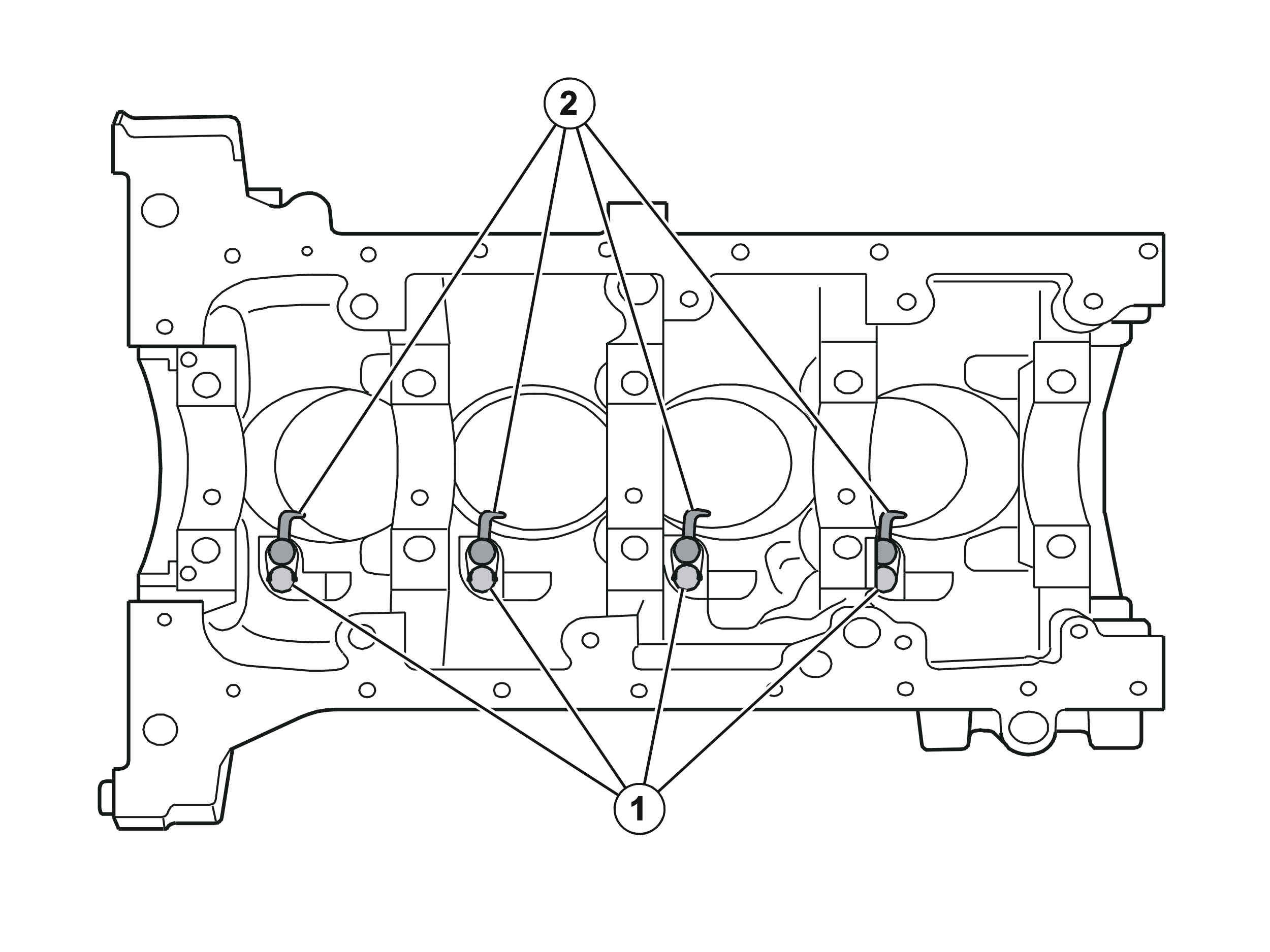
Each cylinder has a nozzle that is secured by means of a screw together with integrated valve. This valve opens at an oil pressure of approximately 50 kPa.
The oil is injected continuously under the piston as soon as the valve has opened.
When the piston is in the lower limit position, the oil is injected into a channel in the piston. The oil passes through the piston and on to the pan.
In this way, the oil transports the heat away from the piston.
Fuel system
Injectors
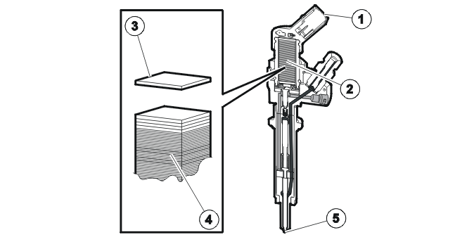
- Connection engine control module (ECM)
- Piezo element
- The piezo element is 0.1 mm thick
- Approximately 450 thin elements on top of each other achieve the necessary change in shape
- Holes, 5.
The engine control module (ECM) calculates the injection time and the injection volume on the basis of various input parameters.
The injectors are activated directly by the engine control module (ECM). The injectors are controlled by changing the shape of the piezoelectric elements.
Via the piezoelectrically controlled injectors, a defined amount of fuel is injected into each combustion chamber. This takes place via priming and one main injection.
The internal feed pump supplies the fuel volume control valve and the flow control valve with fuel. The flow control valve directs surplus fuel back to the intake side of the internal feed pump.
Fuel that is intended to lubricate the high-pressure pump flows from the internal feed pump to the valve for the lubricating channel, on through the high-pressure pump to the fuel return and back to the fuel tank.
The position of the fuel volume control valve determines the amount of fuel that reaches the pump element for the high-pressure pump. The three internal pump elements generate a flow of fuel out to the fuel rail and the injectors.
The pressure in the fuel system is measured using a fuel pressure sensor in the fuel rail. The fuel pressure sensor signal is used by the engine control module (ECM) as an input signal for calculating the amount to be injected.
The fuel pressure control valve regulates the flow out to the fuel rail. As a result, the pressure in the fuel rail can be adapted to each unique operating condition.
The fuel is brought in under high pressure into the fuel rail and to the injectors and is available for injection. The injection pressure varies between approximately 35 MPa and 165 MPa depending on the operating condition of the engine.
The high-pressure control valve on the high-pressure outlet for the diesel pump regulates the fuel pressure and therefore also the pressure in the fuel rail.
Closed injector
Fuel from the fuel rail reaches the upper chamber and the high-pressure chamber. The valve closes the link to the channel for return fuel. The valve is actuated by the fuel pressure and by a spring.
The fuel pressure also acts on the push rod (upper chamber) and the fuel needle (high-pressure chamber).
When the push rod area is greater than the fuel needle area, the push rod force will be greater than the fuel needle force. This causes the fuel needle to close.
Starting injection
When injection is to take place, the piezo material is supplied with power for a brief moment. This causes the material to change shape, which affects the arm and the piston and therefore also the valve.
The valve opens the link to the channel for return fuel, which produces a reduction in pressure in the upper chamber. With the reduced pressure in the upper chamber, the force that acts on the push rod is also reduced.
The pressure remains in the high-pressure chamber, which means that the force that acts on the fuel needle is greater than the push rod force.
The fuel needle lifts and fuel reaches the combustion chamber via the five holes.
Stopping injection
To stop injection, the piezo material is supplied with power for another brief moment with reversed polarity.
The material returns to its original form. The valve closes and the fuel pressure in the upper chamber rises. The force on the push rod increases and exceeds the fuel needle force. The fuel needle closes and injection is interrupted.
Fuel filter
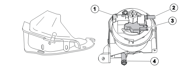
- Inlet from fuel tank
- Connection to diesel pump
- Electrical fuel preheating
- Drain screw.
In the fuel filter there is a unit comprising a bimetallic spring and a heater element. When the key is turned to ignition position II, the central electronic module (CEM) activates a relay and the bimetallic spring is supplied with power. The bimetallic spring switches close the electrical circuit and the element is supplied with power. The current causes the element to heat up, which therefore heats up the fuel.
The circuit works irrespective of whether the engine is running or not.
The fuel filter has a water separator. This must be emptied at regular intervals according to the instructions in the service literature.
Fuel volume control valve
The purpose of the fuel volume control valve is to supply the three pump elements in the high-pressure pump with fuel. The engine control module (ECM) calculates how much fuel is to go to the pump elements, based on factors such as the desired fuel pressure and the desired amount of fuel that is to be injected.
Fuel pressure control valve
The fuel pressure valve regulates the pressure on the high-pressure side of the fuel pump (FP), and therefore also the pressure in the fuel rail. The fuel pressure control valve also damps pressure variations that arise for example when the fuel pump (FP) is delivering fuel and when injection is taking place.
Fuel regulation
The engine control module (ECM) works on the basis of the input signals to process information to control the fuel quantity, injection time and fuel pressure so as to ensure good drivability under all circumstances. Injection takes place over two stages, preignition and main ignition, in order to reduce noise levels and emissions.
Regulating fuel pressure
The three pump elements in the high-pressure pump create a flow at high pressure out to the fuel rail. The amount of fuel going to the high-pressure pump is regulated by the fuel volume control valve. The fuel pressure in the fuel rail is directly dependent on the position of the fuel pressure control valve. The pressure when idling is 28 MPa. Maximum pressure, 165 MPa, is achieved at engine speeds (RPM) above 4000 rpm at full load. The engine control module (ECM) performs this control.
When the engine is switched off, the fuel volume control valve closes while the fuel pressure control valve opens. This means that the fuel system is quickly depressurized. The fuel system does not have a safety valve on the high-pressure side (fuel pump (FP), high-pressure lines and fuel rail). To make the system as safe as possible, the fuel volume control valve closes so that no fuel reaches the high-pressure pump when it is without power, while the fuel pressure valve opens so that the high-pressure pump is drained of fuel.
Additive tank, applies to S40 (04-), V50, C30 and C70 (06-)
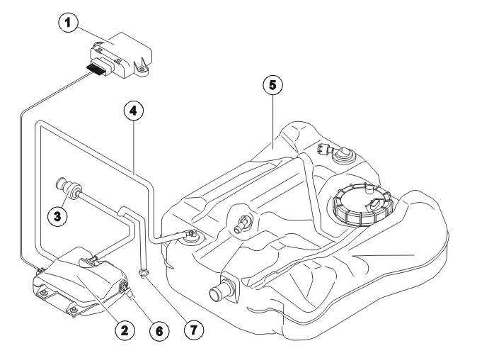
- Additive Dosing Module (ADM)
- Additive tank with integrated pump and level sensor
- Ventilation valve for the tank
- Feeder hose and injector
- Main fuel tank (diesel)
- Overflow valve (when filling)
- Refilling connection for additive
The task of the additive dosing module (ADM) is to calculate and control the quantity of additive dosed to the main fuel tank (diesel) whenever fuel (diesel) is added so as to ensure that emissions requirements can be met.
NOTE: For the additive dosing module (ADM) to start dosing after fueling, more than five liters of fuel (diesel) has to have been added, otherwise no additive will be added to the main fuel tank.
When the engine is started after fueling, the engine receives information on how much fuel has been added. To ensure that the noise from the additive pump is not disruptive, additive dosing will not start until the vehicle reaches a speed in excess of 40 km/h. If this speed is not attained within 4 minutes of fueling, once the engine has been started the first time, dosing will start anyway.
The additive must be topped up at an authorized workshop. It cannot be done by the customer. Additive consumption is normally so low that it normally only need to be topped at regular service intervals. The particle trap, which burns particles from the exhaust gases can become damaged without additive.
When additive is topped up, the mechanic has to transmit a diagnosis command to the additive dosing module (ADM) so that the additive's level counter can be zeroed. See diagnosis functions for more information.
For more information, see Design and Function, Additive Dosing Module (ADM).
EGR system
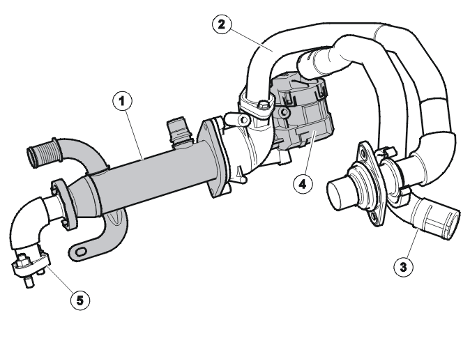
- Exhaust gas recirculation (EGR) cooler
- Connector pipe to intake manifold
- Connector pipe to valve cover / air cleaner (ACL)
- EGR stepper motor
- Connection to the cylinder head.
The EGR valve is electrically controlled by the engine control module (ECM).
EGR technology is used in order to lower the exhaust temperature and therefore to reduce NO x emissions. This means that some of the exhaust gases are recirculated to the combustion chamber.
By allowing the exhaust gases to pass through a cooler where coolant is used as the refrigerant, the temperature of the recirculated exhaust gases is lowered which enables NOxemissions to be further reduced.
The volume of recirculated gases is regulated by an electric motor controlled by the engine control module (ECM). The mass air flow (MAF) sensor signal is used as the main parameter for calculating when exhaust gas recirculation should be allowed.
The recirculated exhaust gas volume is regulated by an EGR stepper motor and can therefore be accurately adapted.
The recirculated exhaust gases are cooled via an EGR cooler before being routed into the intake manifold.
In order to clean the valve of soot and deposits, the valve is activated a number of times each time the engine is switched off.
Turbocharger (TC)
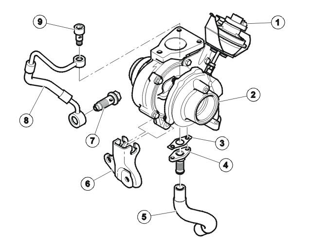
- Turbocharger (TC) position sensor
- Turbocharger (TC) housing
- Gasket
- Adapter
- Oil return hose
- Retainer
- Banjo screw
- Oil line
- Banjo screw
The turbocharger (TC) system on this engine comprises a turbocharger (TC) with VNT (Variable Nozzle Turbine), which is regulated by a turbocharger (TC) control valve. This in turn acts on a pressure regulator. A position sensor transmits information about the position of the turbines to the engine control module (ECM).
In order to achieve optimum torque characteristics, a Garret turbocharger (TC) with variable turbine geometry is used.
The moving guide rails in the turbine are controlled by the turbocharger (TC) pressure regulator via a linkage.
In the middle of the turbocharger (TC) pressure regulator there is a pressure sensor which forwards the position of the guide rails in the form of input signals to the engine control module (ECM).
The vacuum to the turbocharger (TC) pressure regulator is dosed by the solenoid valve for the boost pressure control. The solenoid valve for the boost pressure control is controlled by the engine control module (ECM).
The turbocharger (TC) bearings are lubricated via a pipe from the engine lubrication circuit.
A pressure regulator is connected to the guide rails by means of a rod. A position sensor is located on the pressure regulator. The sensor registers the position of the rod and therefore also the position of the guide rails. The signal from the sensor is used by the engine control module (ECM) to calculate the position of the guide rails and therefore also the boost pressure. The position of the guide rails is regulated by the air pressure in the regulator.
Cooling system
The shut-off valve is located in the supply line from the thermostat housing to the expansion tank. This limits the flow of coolant to the expansion tank when running the engine to operating temperature.
The bypass valve is located between the coolant outlet on the cylinder head and the supply line to the coolant pump. This limits the flow of coolant to the coolant pump when running the engine to operating temperature.
The majority of the coolant is routed to the heat exchanger and flows back to the coolant pump via the EGR cooler.
The bypass valve starts to open at a certain coolant temperature. It remains open until the engine has reached operating temperature.
When the engine reaches operating temperature, the thermostat and the shut-off valve are completely open and the bypass valve is completely closed. At this point, the large coolant circuit is open.
Utilizing the shut-off valve and the bypass valve shortens the warming up time and the passenger compartment temperature can be increased more rapidly.
The bypass valve and the shut-off valve are regulated by the engine control module (ECM).
Coolant circuit
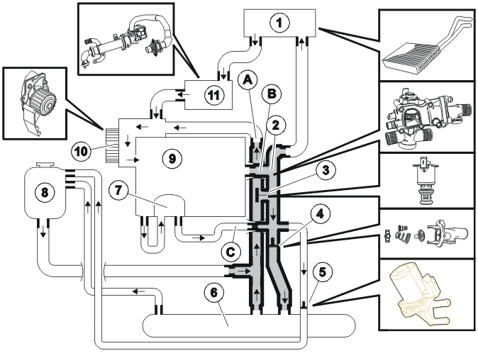
- Heat exchanger
- Thermostat housing
- Bypass valve (S40 (04-), V50 -2005)
- Thermostat
- Shut-off valve
- Oil cooler
- Coolant heat exchanger
- Cooling system expansion tank
- Cylinder block
- Coolant pump
- Exhaust gas recirculation (EGR) cooler
Warm up phase, thermostat closed
During the engine warm-up phase, the thermostat and the solenoid valve are closed. At the same time, the bypass valve keeps the link from the cylinder head to the coolant pump closed.
The coolant only circulates in the small circuit from the cylinder head and from the oil cooler to the heat exchanger in the passenger compartment.
When the coolant temperature rises, the bypass valve opens the link to the coolant pump in proportion to the temperature increase. The coolant now flows to the heat exchanger in the passenger compartment and the intake for the coolant pump. The thermostat and solenoid valve are still closed.
The thermostat starts to open
When the thermostat housing starts to open, the bypass valve closes the link between the cylinder head and the coolant pump proportionally.
At the same time, the solenoid valve gradually opens the link to the expansion tank. The flow from the cylinder head now separates to:
- the passenger compartment heat exchanger
- the inlet for the coolant pump
- the radiator
- expansion tank.
The engine has achieved the correct operating temperature
When the engine has reached the correct operating temperature, the bypass valve completely closes the link between the cylinder head and the coolant pump. The solenoid valve simultaneously opens the link to the expansion tank fully.
A small portion of the coolant now flows through the passenger compartment heat exchanger, while the large flow takes place through the cooler.
Parts & tools for this job For 2006 Volvo C70
- PARTEngine gasket setSearch: Volvo C70 2006 engine gasket set
- TOOLTorque wrenchSearch: 3/8 inch torque wrench
- TOOLFeeler gauge setSearch: feeler gauge set
Links open Amazon search results in a new tab. As an Amazon Associate I earn from qualifying purchases.