
Output signals
- Make
- Volvo
- Model
- S40 Factory Service Manual
- Year
- 1996–2004
- Section
- 09 Miscellaneous › Design and Function › Output signals
0 AdministrationOutput signals
Output signals
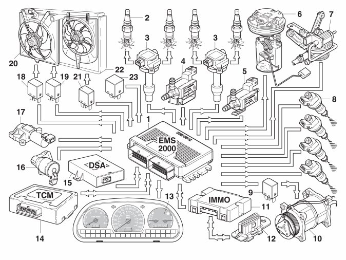
Output signal to | Used for/Remarks | |
| 1 | Engine control module (ECM) | — |
| 2 | Sparkplugs | Ignition takes place at the same time in cylinders 1, 4, and 2, 3. |
| 3 | Ignition coils | Separate coils for cylinders 1/4 and 2/3. New design, coils are located above the sparkplugs for cylinder 3 and 4 and with a cable for 1 and 2, respectively. |
| 4 | evaporative emission system (EVAP) valve | Controls the flow from the canister inlet manifold, or to the turbo during the charging phase. The valve is located on the radiator. |
| 5 | Turbocharger (TC) control valve. | Controls the pressure in the wastegate's control valve. The turbo control valve is located on the air filter housing. |
| 6 | Fuel pump | No separate pump relay. |
| 7 | Leakage diagnosis pump (LDP) | This pump with pressure sensor is located in the rear of the car, beside the fuel tank. |
| 8 | Injectors | Controlled individually. The fuel is shut off at 6,500 rpm as overspeed protection. Shut-off at engine braking over 1,800 rpm. |
| 9 | AC compressor relay | Cut-in/cut-out of AC compressor. Direct control of AC compressor for compensation of high idle rpm. |
| 10 | air conditioning (A/C) compressor. | Activated/deactivated with AC compressor relay. |
| 11 | Control module immobilizer | Electronic immobilizer type 3 based on the challenge-response principle. |
| 12 | Diagnostic socket (DLC) | No direct connection to DLC. Troubleshooting is always done via control module immobilizer. The communication cable between Engine control module (ECM)and Control module immobilizer is used for both diagnostics and immobilizer function. |
| 13 | Combination instrument | Receives a lot of signals from Engine control module (ECM):
|
| 14 | Transmission control module (TCM) | Communication with Transmission Control Module (TCM) takes place via two cables. Signals are based on CAN communication principle. Up to 38 different signals are communicated via this system. Some of the most important are:
From Transmission Control Module (TCM) to Engine control module (ECM):
|
| 15 | Dynamic stabilizer system (DSA), control module | Communication across three cables about engine load, rpm, throttle position, request for torque reduction, and confirmation. Also EMS 2000-system trouble prevention DSA-activation. |
| 16 | Idle valve (IAC) | Idle rpm and limitation of vacuum in inlet manifold during engine braking. No limp-home function. |
| 17 | CVVT | Valve for variable camshaft timing on exhaust side. Same principle as for 5-cylinder engines. Only used for ECT below 60 °C. |
| 18 | Engine cooling fan relay for speed 1 | Turns on and off cooling fan (FC) with first speed. |
| 19 | Engine cooling fan relay for speed 2 | Turns on and off cooling fan (FC) with second speed. |
| 20 | Engine cooling fan | Cools the engine's radiator. Two speeds. |
| 21 | Relay for condenser fan | Turns on/off the condenser's fan |
| 22 | Condenser cooling fan | Only on cars with AC |
| 23 | System relay | Feeds current to:
|
Parts & tools for this job For 1996 Volvo S40
- TOOLTorque wrenchSearch: 3/8 inch torque wrench
- TOOLSocket setSearch: socket set metric
- BOOKHaynes manualSearch: Haynes manual Volvo S40
Links open Amazon search results in a new tab. As an Amazon Associate I earn from qualifying purchases.