
Synchronizer
- Make
- Volvo
- Model
- S40 Factory Service Manual
- Year
- 1996–2004
- Section
- 43 Transmission › Design and Function › Synchronizer
4 Power transmissionSynchronizer
Synchronizer
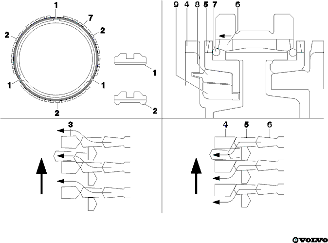
| 1. Position without extension. | 6. Synchronizer sleeve. |
| 2. Position with extension. | 7. Synchronizer spring. |
| 3. Conventional shape clutch gear. | 8. Synchronizer cone 2nd speed. |
| 4. One-way chamfered clutch gear. | 9. Inner synchronizer ring 2nd speed. |
| 5. Outer synchronizer ring 2nd speed. |
Keyless synchronizer
- This synchronizer is keyless, This means that the leaf spring-loaded rollers are discontinued
- This synchronizer has a sleeve that has three extensions to the inside (center) of its circle. These positions are marked 2. These extensions are “opposite” the extensions of the synchronizer ring. These positions are marked 1
- At positions 1 the synchronizer spring, which is a simple steel O ring, comes into contact with the synchronizer ring. 2nd gear however comes into contact with the outer synchronizer ring
- When a shift is started, the synchronizer sleeve moves in the direction of the synchronizer ring. The extensions from the sleeve push the central spring towards the ring. The ring in turn will increase the friction with the clutch gear and start the synchronizing function
- The synchronizer sleeve deforms the spring as it moves on. The ring deforms slightly as a triangle
- Just before the synchronizer sleeve comes into contact with the chamfered parts of the synchronizer ring tooth, a large force is generated which pushes the synchronizer ring against the clutch gear. This gives a strong synchronizing function
- Thereafter the synchronizer sleeve comes into mesh with the clutch gear and the shift is completed.
Double synchronizer ring in 2nd gear
- On the 2nd gear two synchronizer rings are used to provide an improved synchronizing function. The outer and inner synchronizer ring have the same rotation speed. They are geared into each other. Both have their synchronizing function on the loose synchronizer cone. This cone is geared with the gearwheel of the 2nd gear by four pin coming into the gearwheel. A double synchronizing function is accomplished.
One-way flow chamfering
- After the synchronizing function has been completed by the synchronizer mechanism, the synchronizer sleeve passes through the synchronizer ring and comes into mesh with the clutch gear. Just before this point, when the synchronizer ring is not pressing against the clutch gear, the clutch begins to move against the synchronizer sleeve
- With its conventional chamfered shape (3), the synchronizer sleeve pushes the clutch gear in the opposite direction to the rotation direction of the clutch gear. The clutch gear has to push back the synchronizer sleeve which results in resistance at the time of shifting
- To reduce this resistance, the chamfered part of the 2nd and 3rd clutch gear have been changed (4) to form a one-way flow. As a result the rotation direction does not interfere and meshing take place with less resistance. Therefore shifting requires less force.
Parts & tools for this job For 1996 Volvo S40
- TOOLTorque wrenchSearch: 3/8 inch torque wrench
- TOOLSocket setSearch: socket set metric
- BOOKHaynes manualSearch: Haynes manual Volvo S40
Links open Amazon search results in a new tab. As an Amazon Associate I earn from qualifying purchases.