
Engine – Design
- Make
- Volvo
- Model
- S40 Factory Service Manual
- Year
- 2004–2012
- Section
- 09 Miscellaneous › Design and Function › Engine – Design
Engine – Design
NOTE: Since the illustrations in this service information are used for different model years and/or models, some variation may occur. However, the essential information is always correct.
Engine, general
See: Engine, general
Lubrication system
Oil pump
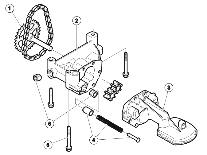
- Oil pump chain wheel
- Oil pump housing
- Oil screen
- Pressure reduction valve
- Mounting screws
- Blind cover plug.
The oil pump is located on the transmission side of the engine, in the oil trough.
An oil pressure control valve is built into the oil pump housing. This valve opens at an oil pressure of approximately 800 kPa.
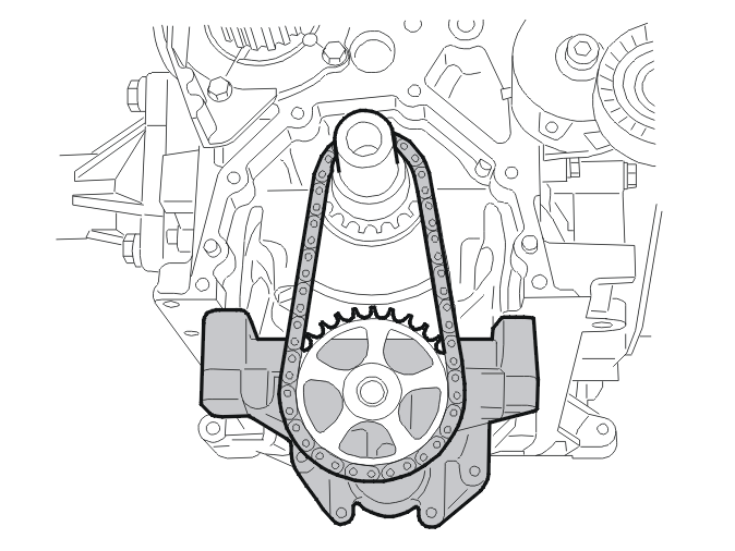
The oil pump is a rotor pump. It is powered by the camshaft via a short chain.
Oil filter
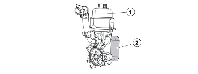
- Oil filter housing
- Oil cooler
The oil filter is a filter insert. There is a duct in the oil filter housing that is exposed when the oil filter is disassembled. Any remaining oil runs down into the oil pan and further spillage is eliminated.
The oil cooler is a plate oil cooler. The unit is connected to the coolant system. The coolant is routed through the oil cooler and on to the thermostat housing.
The oil cooler is also a coolant heat exchanger. The unit is located on the side of the cylinder block, level with cylinder 2.
There is a blind cover plug on the oil filter insert for sealing the drain hole for the oil filter housing.
When replacing the oil filter cartridge, the plug is pulled out together with the oil filter cartridge. The oil can run back to the oil trough via the housing, which mean that contaminants through leaking oil are prevented.
The unit is connected directly to the engine cooling system via a connection and a hose.
Oil pressure switch
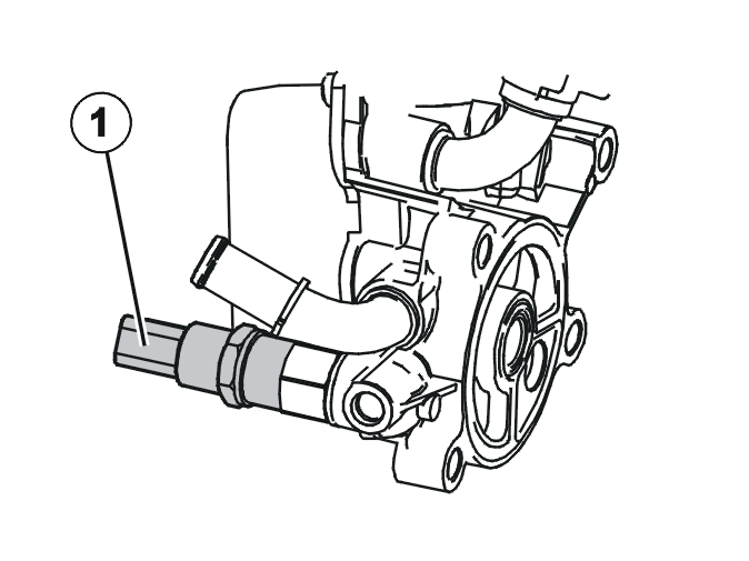
- Oil pressure switch
The oil pressure switch is located to the right by the oil cooler.
The minimum oil pressure of 50 kPa is monitored via the oil pressure switch. If this pressure is not achieved, the oil filter remains closed for safety reasons. The switch is connected via a conventional cable to the engine control module (ECM).
Oil injection pipes
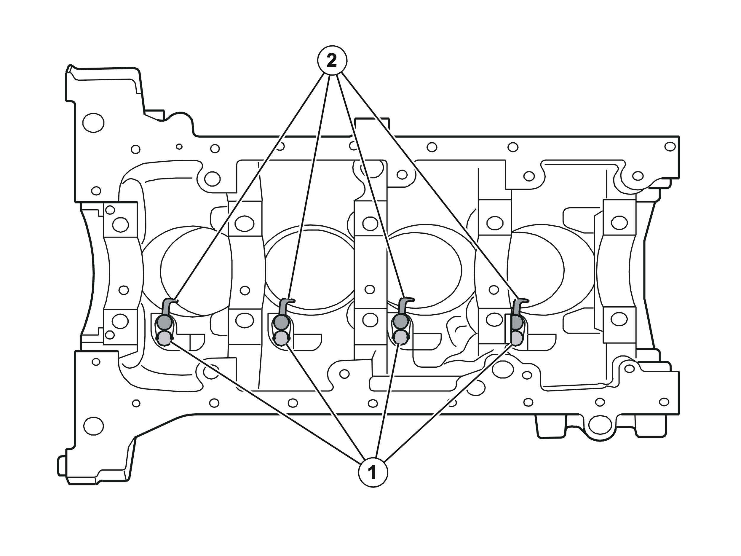
- Banjo screws
- Oil injection pipes
The piston heads are cooled from beneath with oil from the oil injection pipes. The oil injection pipes are secured with banjo screws in the cylinder block.
The banjo screws are connected to the engine lubrication circuit.
The banjo screws contain valves that open the supply to the oil injection pipes when the oil pressure is approximately 50 kPa.
Fuel system
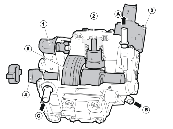
1. Fuel volume control valve
2. High pressure pump
3. Fuel pressure control valve
4. Drive shaft with eccentric
5. Internal feed pump
A. Fuel return
B. Connection for fuel rail
C. Inlet from the tank
The pump consists of the following main components:
- Internal feed pump that draws fuel from the tank via the fuel filter to the high-pressure pump. The feed pump also supplies the high-pressure pump with fuel for lubrication. The pump is a vane-type pump
- The fuel volume control valve, which regulates the fuel flow to the high-pressure pump according to the current need
- The high-pressure pump, which supplies the fuel rail and the injectors with fuel at high pressure
- The fuel pressure control valve, which regulates the fuel pressure from the high-pressure pump before the fuel reaches the fuel rail and the injectors.
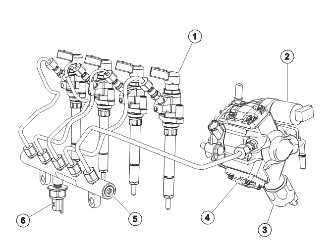
- Injector
- Fuel dosing valve
- High-pressure control valve
- Diesel pump
- Fuel rail
- Fuel pressure sensor.
The engine has a common rail injection system from Siemens.
The diesel pump contains an integral feed pump, which feeds the fuel from the tank to the diesel pump.
Diesel pump
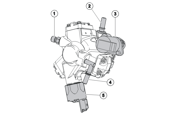
- High-pressure outlet for fuel rail
- Inlet from fuel filter
- Fuel volume control valve
- Return to fuel tank
- High-pressure control valve
The diesel pump is located on the transmission side of the cylinder head and is powered directly by the exhaust camshaft via a flange.
The diesel pump has three high-pressure pump elements that are located with a 120° separation.
The feed pump is integrated in the diesel pump and is located on the flange. The feed pump is a vane-type pump.
The fuel dosing valve is located in the inlet channel between the high-pressure pump elements and the feed pump. It is controlled via pulse width modulation by the engine control module (ECM).
The three high-pressure outlets for the high-pressure pump elements have been brought together into a single high-pressure connection.
The high-pressure control valve is located by the high-pressure bore for the fuel rail. The fuel pressure regulator is activated by the engine control module (ECM).
Fuel rail
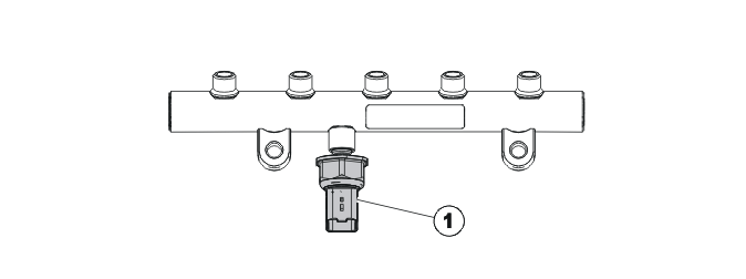
- Fuel pressure sensor.
CAUTION: The fuel pressure sensor in the fuel rail must not be loosened or removed.
The fuel rail is made from forged steel and is mounted directly in the cylinder block.
The fuel is supplied from the diesel pump to the fuel rail via a single delivery line.
From the fuel rail, the fuel is led to the injectors via four more delivery lines.
Fuel filter
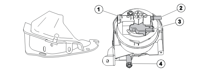
- Inlet from fuel tank
- Connection to diesel pump
- Electrical fuel preheating
- Drain screw.
The fuel filter is located above the fuel rail and is mounted in a holder on the cylinder head.
The fuel filter has electrical fuel preheating, which is located in the middle of the filter, between the inlet and the outlet connections.
The fuel filter and the housing constitute a single unit that can only be replaced as a complete unit.
The fuel filter has collision protection.
Injectors
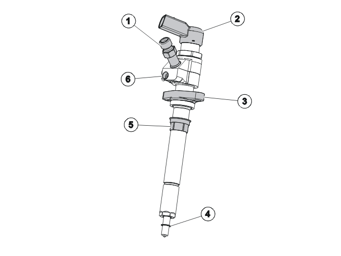
- Delivery line connection
- Connector
- Retainer
- Copper seal
- Plastic socket
- Return line connection.
The injectors are located in the center of the top of the cylinder head, and are secured in holders.
The guide sleeves in the lower section of the cylinder head and the plastic sleeves for the injectors provide correct centering.
The seal with the combustion chamber is provided with a copper washer between the injector and the cylinder head. This must always be replaced when installing.
The return lines are secured on the top of the injectors and connected in series to each other.
The use of piezoelectrical material for controlling the injection sequences provides a number of benefits compared to injectors that work with electromagnetism:
- up to four times faster
- only one impulse is required to start injection and one impulse to terminate injection
- low power consumption
- the combination of low current and impulse control means that less energy is required for each injection sequence
- the speed means that the injection times can be controlled extremely precisely, which ensure great accuracy as regards the amount of injected fuel
- the system is not sensitive to electromagnetic effects.
Additive tank, applies to S40 (04-), V50, C30 and C70 (06-)
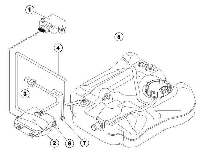
- Additive Dosing Module (ADM)
- Additive tank with integrated pump and level sensor
- Ventilation valve for tank
- Feeder hose and injector
- Main fuel tank (diesel)
- Overflow valve (when filling)
- Refilling connection for additive
The additive system consists of the additive dosing module (ADM), additive tank, a mechanical injector on the main fuel tank and the feeder hose for additive.
The additive tank is made of polyethylene plastic.
The additive tank has a refilling connection for additive and a ventilation valve. The tank has an overflow valve. This valve releases any excess additive during refilling when the tank is full. There is a pump and level sensor inside the additive tank.
The pump is integrated in the additive tank. It is positioned on the side of the tank housing. The pump cannot be replaced as a separate component. The entire additive tank must be replaced as a single unit.
The level sensor provides the additive dosing module (ADM) with information about the prevailing additive level in the separate tank. The level sensor is integrated in the additive tank. It is positioned on the bottom of the tank housing. The level sensor cannot be replaced as a separate component. The entire additive tank must be replaced as a single unit.
For more information, see Design and Function, Additive Dosing Module (ADM).
Vacuum system
Overview
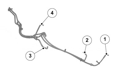
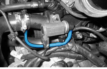
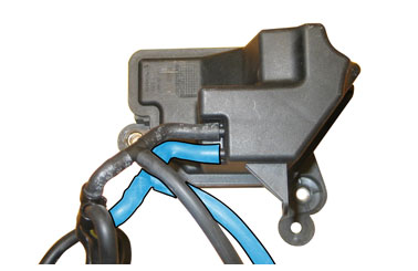
CAUTION: All hoses connected to the vacuum tank shall be connected to the outer connection on the actuators.
NOTE: Hose 1 and hose 2 are connected to the vacuum tank.
NOTE: Hose 3 is yellow-marked.
Hose 1
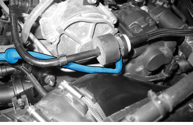
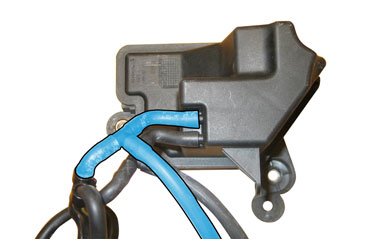
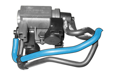
Hose 2
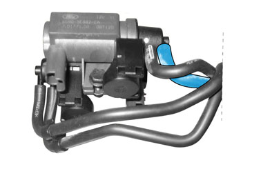
Hose 3
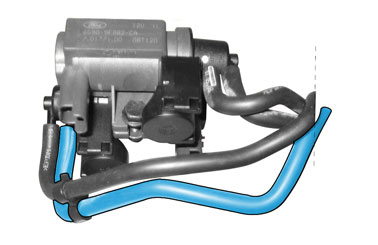
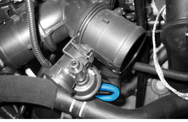
Hose 4
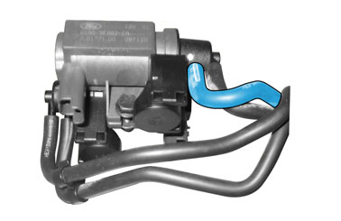
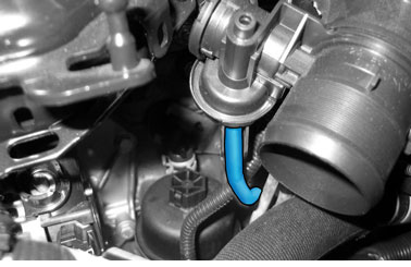
EGR system
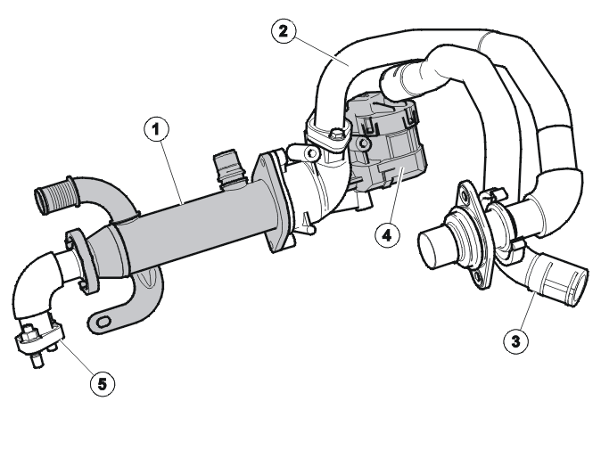
- Exhaust gas recirculation (EGR) cooler
- Connector pipe to intake manifold
- Connector pipe to valve cover / air cleaner (ACL)
- EGR stepper motor
- Connection to the cylinder head.
The EGR system consists of an EGR stepper motor, and EGR cooler and a connector pipe to the intake manifold.
Catalytic converter
The catalytic converter is an oxidation catalytic converter which reduces CO and HC emissions.
Its location, immediately after the turbocharger (TC), known as a CCC (Closed Coupled Catalyst), means that the catalytic converter rapidly reaches the correct operating temperature.
Turbocharger (TC)
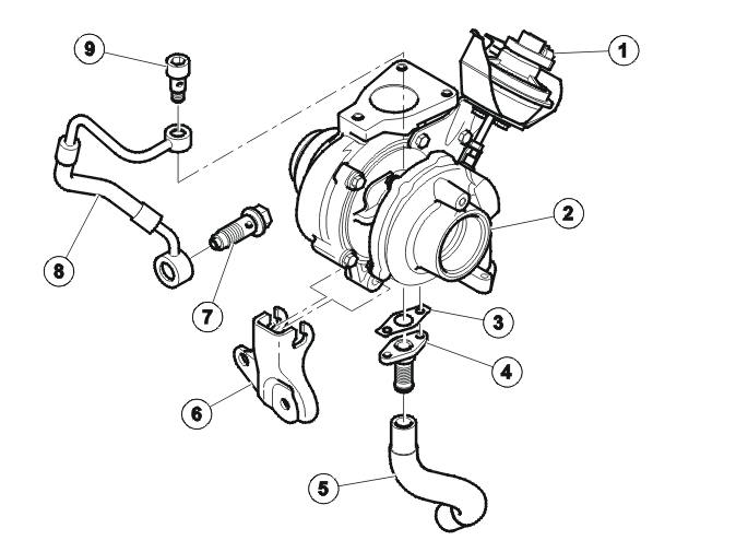
- Turbocharger (TC) position sensor
- Turbocharger (TC) housing
- Gasket
- Adapter
- Oil return hose
- Retainer
- Banjo screw
- Oil line
- Banjo screw
The turbocharger (TC) control valve steplessly regulates the vacuum in the pressure regulator which control the turbine position, (Variable Nozzle Turbine, VNT).
In principle the valve can vary the pressure from absolute vacuum to atmospheric pressure. This allows the guide rails for the turbocharger (TC) to be regulated steplessly, which means that the desired boost pressure can be achieved.
The engine control module (ECM) controls the position of the control valve and hence also the position of the valve.
Cooling system
Coolant circuit
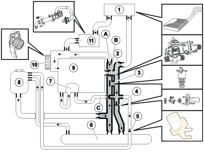
- Heat exchanger
- Thermostat housing
- Bypass valve (S40 (04-), V50 -2005)
- Thermostat
- Shut-off valve
- Oil cooler
- Coolant heat exchanger
- Cooling system expansion tank
- Cylinder block
- Coolant Pump
- Exhaust gas recirculation (EGR) cooler
The coolant flow is dependent on the following components:
- bypass valve (3)
- thermostat (4)
- shut-off valve (5)
- engine coolant temperature (ECT) sensor
- engine control module (ECM).
Due to the high efficiency of the diesel engine and consequently the relatively small heat losses, it can be difficult to maintain a comfortable temperature in the passenger compartment at low outside temperatures. The purpose of the various components is, on the basis of the coolant temperature, to regulate the coolant flow to the heater element in the passenger compartment so that coolant heating takes place as quickly as possible.
Thermostat housing
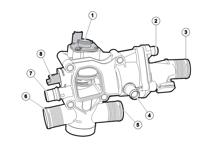
- Bypass valve
- Connection to the cooling system expansion tank
- Connection to cooler inlet
- Connection to coolant heat exchanger
- Connection to cooler outlet
- Connection to coolant pump
- Connection to heat exchanger
- Engine coolant temperature (ECT) sensor.
WARNING: The engine temperature sensor (ECT) must not be removed as long as there is pressure in the cooling system.
In order to achieve rapid heating of the coolant, and therefore a comfortable temperature in the passenger compartment, the engine cooling system has:
- a thermostat housing
- an electrically controlled bypass valve
- an electrically controlled shut-off valve.
The thermostat housing is located on the cylinder head on the transmission side of the engine.
The engine temperature sensor is located in the thermostat housing and is secured with a clip. The thermostat housing also houses the thermostat and the bypass valve. The thermostat is a conventional type.
The thermostat housing is made of plastic and cannot be dismantled during service work. The engine coolant temperature (ECT) sensor can be replaced separately.
For further information about the components, see Design and Function, engine control module (ECM).
Coolant Pump
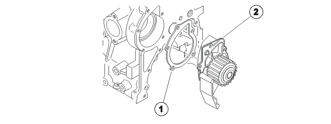
- Gasket
- Coolant Pump
The coolant pump is located on the transmission side of the engine and is powered via a toothed belt.
The coolant pump housing consists of an aluminum alloy and is secured using 5 screws.
The pump housing is made of an aluminum alloy. The gear wheel is made of plastic. The gasket between the pump and the cylinder block comprises a metal frame that is coated with rubber.
A rubber-coated metal gasket is used for the coolant pump seal with the cylinder block.
Engine, general
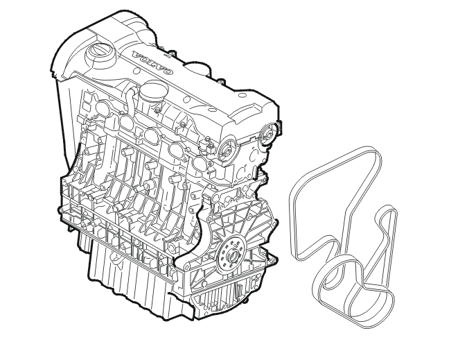
The entire engine is made of aluminum.
The compact "pent roof" design of the combustion chamber and the V shaped arrangement of the valves optimize injection and evacuation via the intake passage and combustion chamber (cross-flow) and the exhaust passage. The swirl surfaces of the combustion chamber and the centrally positioned spark plug ensures optimal combustion, low sensitivity to knocking and low, stable exhaust emissions.
The pendulum suspension of the engine consists of an engine pad secured to a side member. The cylinder head is "gravity" cast which is a slower process than press casting. This is so that the exhaust and intake ducts and the water and oil mantles are integrated during construction.
Applies from 2006 model year
The engine meets Euro 5 emissions standards.
All bearings are lead free. The screws used are Crome 6+ free.
Cylinder head, camshaft bearing housing
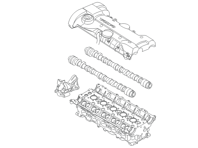
The engine block is divided up into five sections. The cylinder head consists of two sections and the cylinder block of three sections. The seal between the cylinder head and cylinder block is a conventional cylinder head gasket. The seal between the other gasket faces is a liquid gasket.
There is a cover over the sparkplug wells for protection against dirt and water. The two camshafts are carried on six bearing caps each in the two halves of the cylinder head. The upper half is a combined valve and camshaft cover.
It has cast oil ducts on the underneath which ensure good oil supply to the camshafts and the mechanical valve lifters. The lower half contains the maintenance-free mechanical valve lifters, the valve springs and valves.
Cylinder block
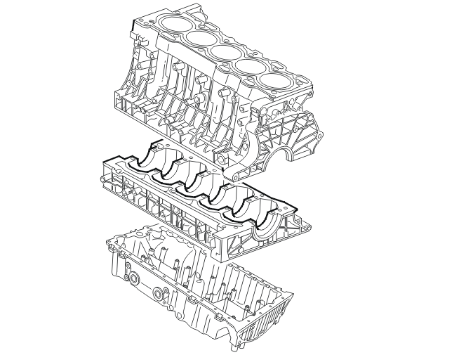
The engine block is divided into three sections, the cylinder block, intermediate section and oil pan. The mating flange between the cylinder block and intermediate section is in the center line of the crankshaft.
The cylinder block has five cast iron cylinder sleeves cast into the cylinder block which cannot be replaced. The six main bearing seats have cast iron reinforcements in the intermediate section.
On the top of the intermediate section there are cast oil channels which distribute the oil to the main bearings and on via the crankshaft to the big ends.
The oil pan contributes to the rigid construction and acts as additional reinforcement. There is central smooth-bore oil duct for piston cooling.
Oil pan
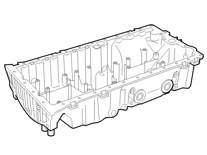
The oil pan is made of die cast aluminum with baffles. This is so that the oil does not splash excessively. It is secured in the cylinder block with a liquid LOCTITE gasket, which ensures the seal between the cylinder block and oil pan.
Crankshaft
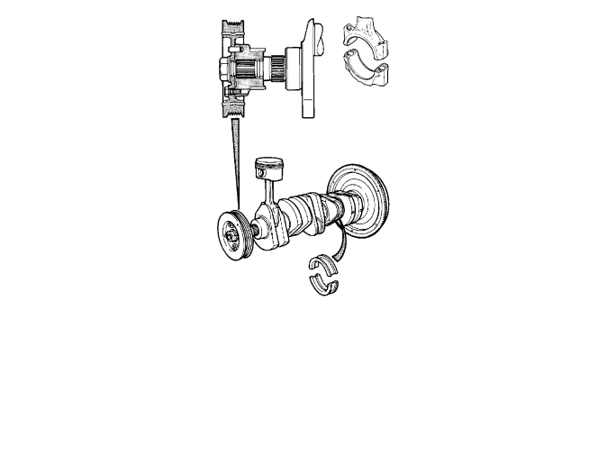
The crankshaft has six main bearings. The 5th main bearing is a throw-out bearing. At the front end of the crankshaft are two spline joints, the inner of which drives the oil pump. The drive gear for the timing belt and vibration damper is on the outer joint.
A blind spline ensures that the position and control of the drive gear is correct. The connecting rods are forged and the split joint between the connecting rods and the caps gives an exact mounting to the caps.
B5244SX and B5254TX are both equipped with forged crankshafts which give maximum strength and contribute to a low noise level.
Piston
The piston has a homogenous aluminum alloy with graphite coating on the sides. This coating gives reduced friction and noise. The piston rings are of different materials depending on where they are located on the piston. The upper compression ring is a nitrated steel ring. The lower compression ring is manufactured from cast iron and the oil scraper ring is a three piece design, all made of nitrated steel (does not apply to B5xx4Sx). For B5244S7 engines the oil scraper ring is two piece instead of three piece. It is more wear resistant than the three piece ring. The ring height is 2.5 mm compared to 2.0 mm for the three piece ring.
The piston pin is hardened steel and is held together using steel snap rings. The piston is oval and conical and flat at the top. By reducing the area from the upper piston ring to the top of the piston, the release of hydro-carbons from the engine to the three-way catalytic converter (TWC) is reduced.
The pistons are oil cooled so that they can have a lower compression height. Oil is led through a valve in a longitudinal channel in the lower section of the cylinder block on the exhaust side. There is a nozzle screwed to the channel at each cylinder. This leads the oil towards the underside of the piston.
Camshafts, Valve system
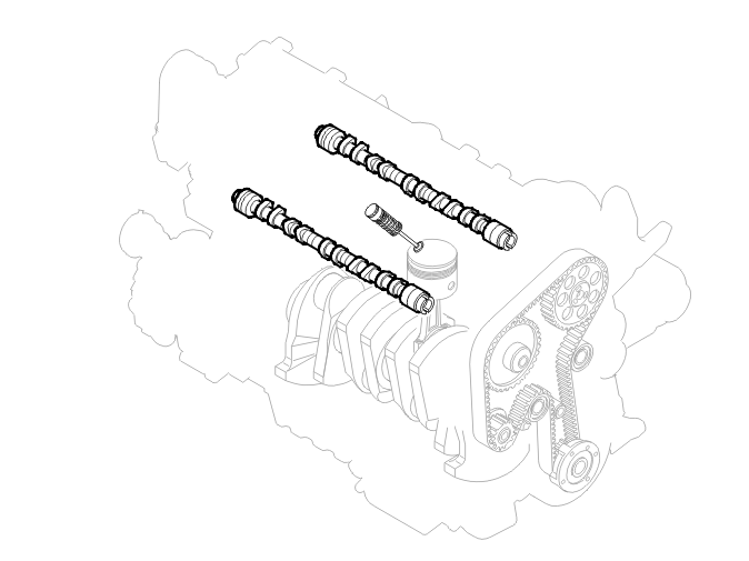
The camshafts are cast iron. The cam lobes which press against the valve lifters are hardened to tolerate the contact pressure. The valve lifters are steel and mechanical, not hydraulic.
There is a certain amount of valve clearance between the valve lifters and cam lobes. The valve clearance is adapted to compensate for differences in length between the valve and cylinder head due to expansion when warming up. Mechanical valve lifters ensure more precise valve timing, reduced friction, more stable combustion and reduced mass.
The material in the lifters is case-hardened steel. The surfaces between the camshaft and valve are slightly convex to guarantee centered contact.
Camshaft transmission
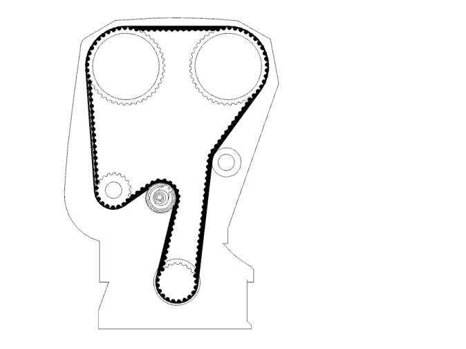
The timing belt which drives both the camshafts and the coolant pump is a conventional single tooth belt. The camshaft's pulley wheels are secured by three screws in each camshaft. The holes for the screws are oval to allow the correct setting of the camshaft positions.
The timing belt tension is retained by a mechanical belt tensioner. The belt tensioner presses the belt via a tensioner roll installed on a lever. The idler wheel on the other side of the belt prevents the belt from swinging.
Auxiliaries belt
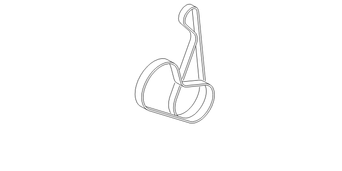
The auxiliary equipment consists of two belts and two auxiliary units. The auxiliary units (generator (GEN), Air conditioning (A/C) compressor) are driven by two Poly-V drive belts tensioned by a mechanical tensioner. The belt tensioners are all located on a bracket that connects the auxiliary units (generator (GEN), Air conditioning (A/C) compressor).
The generator (GEN) receives its power via the air conditioning (A/C) compressor and the air conditioning (A/C) compressor receives its power through the vibration damper which is located on the crankshaft. The power steering pump is driven by an electrical hydraulic pump.
Mechanical timing belt tensioner

The tensioner consists or a spring and a friction element. The friction element provides the required damping to absorb small oscillations and speed variations. The spring ensures correct belt tension, irrespective of wear and temperature. The belts are made of cord reinforced rubber.
Lubrication system
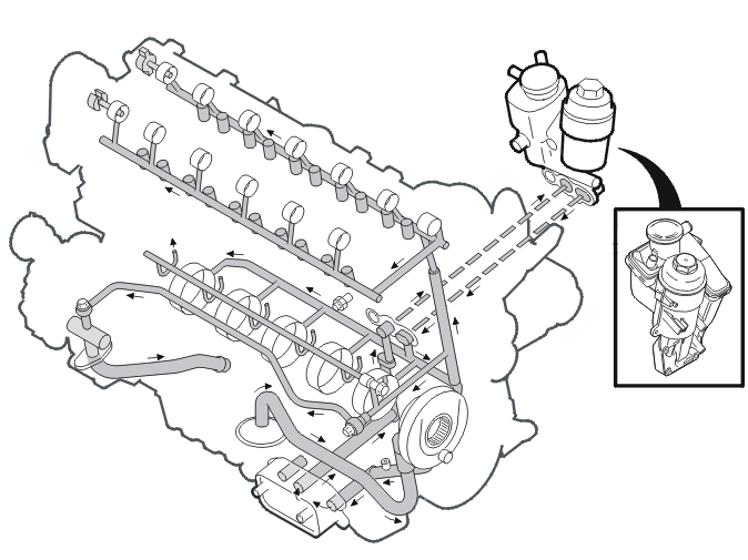
The oil is led from the oil pan via a suction piece to the oil pump. The oil pump is located on the cylinder block. The oil is then pumped onwards to the oil cooling system and then to the oil filter. The oil flows from the filter through a cast oil duct in the intermediate section to the main bearings. The oil then flows through drilled channels in the crankshaft to the connecting rod bearings.
The camshafts are supplied with oil by a bored channel in the cylinder block. The channel runs through the cylinder head, where it flows out at the bottom of the upper half of the cylinder head. There is a cross duct in the channel to the cylinder head which carries oil to the pistons via a piston cooling valve.
The oil flows on via an oil duct to the bearing for the left-hand camshaft and the valve lifters (intake side). The bearings for the right-hand side camshaft (exhaust side) are supplied by a cast cross duct at the front edge of the upper half. This cast cross duct also supplies pressurized oil to the solenoids for the VVT unit. Drain holes in the cylinder block release the oil from the cylinder head and crankshaft bearing back to the oil pan.
Oil filter
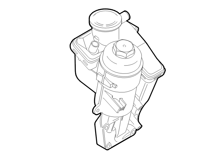
The oil filter holder is made of die cast aluminum. It is on the cold side of the engine. The oil filter cover is plastic. There is a by-pass valve in the cover. A O-ring in the cover ensures that it is sealed.
Piston cooling valve

The piston cooling valve is manufactured in steel with a hardened piston, a spring and a spring stop. A copper washer ensures that oil does not leak onto the cylinder block.
Injector
The valve is enclosed in a plastic casing with O-rings on each end which act as seals. There is a coil in the valve which creates a magnetic field. This overpowers the force of the spring which holds the fuel needle in place. The fuel is let through and mixes with the intake air.
Evaporative emission (EVAP) system
The housing for the evaporative emission system (EVAP) valve is plastic and contains a solenoid valve. The evaporative emission system (EVAP) canister consists of a plastic holder with active carbon and a filter. Internally, the plastic holder is divided up into chambers depending on the market and the prevailing emissions requirements.
All the active carbon in the canisters is held by springs and pressure plates so that no air columns are created by vibration for example. This could lead to hydrocarbon leakage at the carbon beds. The connector pipe has a filter so that carbon dust cannot leak out and damage the leak diagnostic pump and the EVAP valve.
The leak diagnostic pump consists of a plastic housing with an electric motor, pump, valves, leak calibration and a PTC heater element.
Intake system
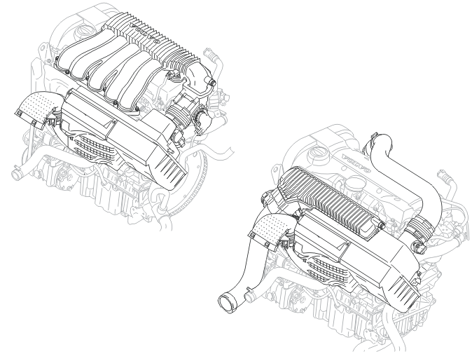
The intake system is divided into two sections, the upper and lower intake manifolds. The upper intake manifold is made of plastic for naturally aspirated and turbocharged engines. The lower intake manifold is aluminum for both types of engine to protect the fuel injection nozzles in the event of a collision.
The intake system for naturally aspirated engines has a total volume of 5.3 liters with fixed barrel lengths. On turbocharged engines the total volume is 3.0 liters with short barrels.
The gasket between the lower intake manifold and cylinder head on naturally aspirated engines is a calibrated single gasket. On turbocharged engines there is a double gasket with a built in non-return valve.
Throttle body (TB)
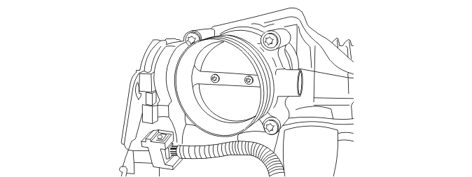
The throttle body (TB) is die cast aluminum. The throttle disc is brass on naturally aspirated engines and aluminum on turbocharged engines. The position sensors are under the plastic cover. These read the position of the throttle disc. There are also two connections to the engine in the cover. These turn the throttle disc to the angle requested by the driver.
The throttle body (TB) does not need to be cooled, but may need to be heated. An O-ring in the intake manifold ensures the seal between the intake manifold and throttle body (TB).
Turbocharger (TC)
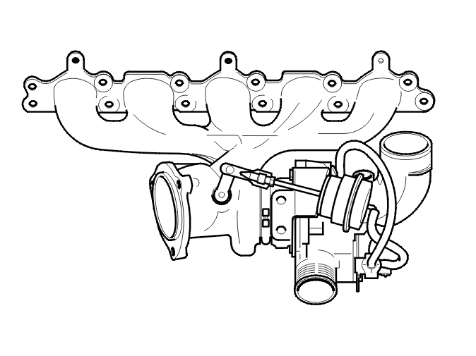
The integrated manifold and turbine housing are made of austenite forged steel to tolerate exhaust temperatures up to 1050 °C.
The bearing housing and turbine housing are held together by a V-shaped clamp. The compressor housing is made of die cast aluminum. The bearing housing is cooled by the oil and coolant system to prevent coking in the bearing for the turbine shaft which spins at up to 170,000 rpm.
Exhaust system
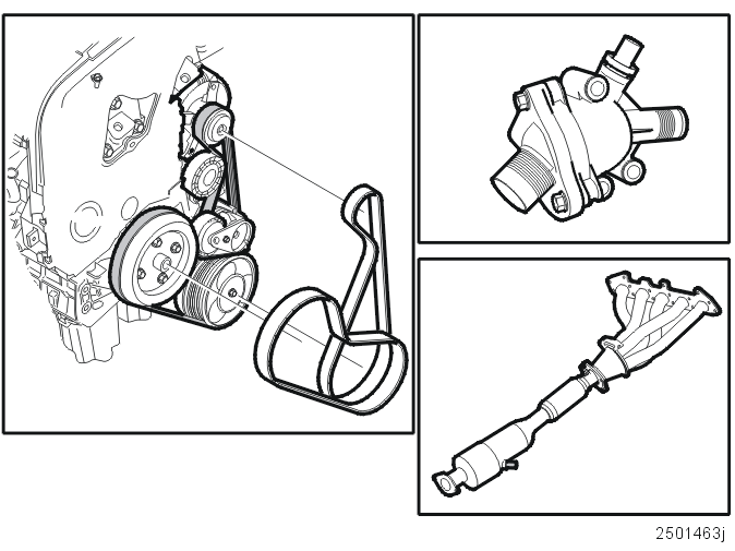
The exhaust system primarily consists of four sections. Manifold (and turbocharger (TC) if the engine is turbocharged), three-way catalytic converter (TWC), heated oxygen sensors (HO2S) and muffler. The exhaust system is manufactured from chromium steel sections welded together.
The pipes are specific lengths so that the gases flowing from the cylinders do not interfere with each other and so that there is good flow distribution in the three way catalytic converter (TWC). There is a boot on the three way catalytic converter (TWC) to absorb engine movements and any manufacturing and installation tolerances.
Heated oxygen sensors (HO2S) are used to control the engine and monitor the three way catalytic converter (TWC). One heated oxygen sensor (HO2S) before and one heated oxygen sensor (HO2S) between the stones. In the B5244S7 an additional heated oxygen sensor (HO2S) is located in the manifold.
The entire exhaust system is manufactured in chromium steel. A three-way catalytic converter (TWC) consists of perforated ceramic beads or metal substrates. These are coated with a washcoat. The washcoat contains precious metals among other things.
Flame trap
The flame trap is made of die cast aluminum and integrated with the oil filter. The cyclone separators are plastic and cannot be replaced.
Cooling system
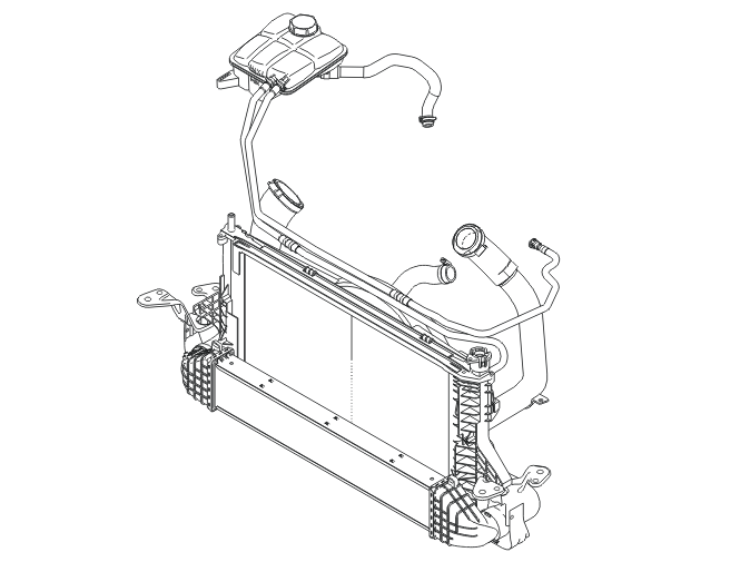
The coolant pump pumps coolant through the cylinder block, and also cools the cylinder head, cylinder sleeves, spark plug wells, intake ducts and fuel injection nozzles.
The coolant flows in at the pump and passes through a number of channels before it collects and then flows out to the thermostat housing. If the thermostat housing is closed, the coolant passes via the by-pass channel directly to the coolant pump to then circulate through the cylinder block again.
In principle, its appearance is the same as the oil cooler for the transmission. Both have an inlet and outlet. The oil cooler is constructed in layers where water and oil flow around each other. Having flowed through the restrictions in the oil ways, the pressure in the system falls.
When the fuel combusts in the engine, the result is both mechanical work and excess energy. The excess heat is taken away from the engine via the exhaust gases by convection to the air in the engine compartment and also by transfer to the coolant and engine oil. The cooling system is a closed system.
B5244S6
Engine B5244S6 has a Premair sensor on the cooling system. This sensor is described in design and function, engine control module (ECM).
Radiator
The radiator is made of aluminum to tolerate the thermal variances when the radiator is being both cooled by cool air and heated by hot coolant.
Thermostat
The thermostat is in the thermostat housing which is in the connection to the coolant outlet from the cylinder head. At the heart of the thermostat is a wax body which expands with energy in the form of heat. In modern cooling systems, the thermostat begins to expand when the surrounding coolant temperature is 90 °C.
Engine, general
See Engine, general.
Lubrication system
Oil pump
The oil pump is located around the crankshaft on the engine's belt transmission side, in the oil pan.
An oil pressure control valve is built into the oil pump housing and opens at an oil pressure of approx. 800 kPa.
The oil pump is a rotor pump and is driven directly by the crankshaft.
Oil filter
The oil filter is an insert filter. The oil filter housing contains a channel that is revealed when the oil filter is removed. Any oil remaining then runs down into the sump and external spillage is eliminated.
The oil cooler is a flat heat exchanger. The unit is connected to the coolant system. The coolant is fed through the oil cooler and on to the thermostat housing.
The unit is located on the side of the cylinder block at the level of the no. 2 cylinder. On the oil filter insert is a cover plug for sealing the oil filter housing drain hole.
The plug is pulled out with the oil filter cartridge when the oil filter cartridge is replaced. The oil can run back to the oil pan via the housing so as to prevent contamination on account of leaking oil. The unit is directly connected to the engine's cooling system via a connector and a hose.
Oil pressure contact
The oil pressure contact is on the right of the oil cooler.
The oil pressure contact opens at a pressure in excess of 50 kPa and the oil pressure light goes out. The job of this lamp is to indicate to the driver that the engine has oil pressure. The contact is connected via a conventional line to the engine control module (ECM).
Piston cooling jets
The tops of the pistons are cooled from below using oil from the piston cooling jets. These are mounted in the cylinder block.
The piston cooling jets are connected to the engine's lubricant circuit.
The piston cooling jets contain valves which open the supply to the oil spray tubes at an oil pressure of approx. 50 kPa.
Induction and exhaust system
Induction system
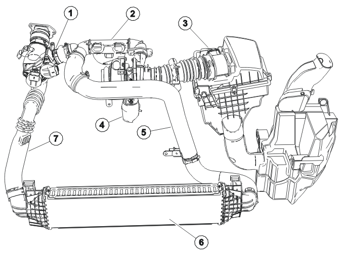
- Induction pipe flap housing
- Bypass channel for charge air cooler
- Mass airflow meter
- Turbocharger vacuum box for VNT control
- Connecting pipe to turbocharger/charge air cooler
- Charge air cooler
- Connecting pipe from charge air cooler
- Charge pressure sensor
- Induction temperature sensor
In addition to the induction pipe flap in the basic engine, there is also a bypass pipe for the charge air cooler. This is adjusted by means of a stepper motor when the particle filter is cleaned.
The bypass channel for the charge air cooler connects the turbo's output directly to the induction pipe flap housing, so circumventing the charge air cooler.
The stepper motor for the induction pipe flap is controlled by the engine control module (ECM) using pulse width modulation.
Another function is to prevent jerking when the engine is switched off.
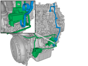
Vacuum system
Hose 1
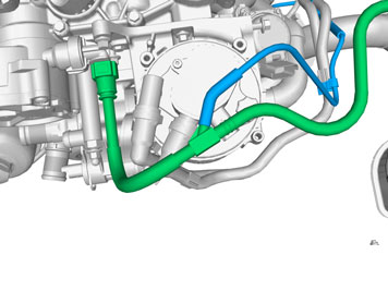
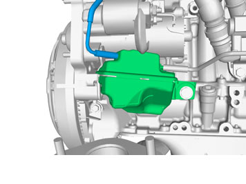
Hose 2
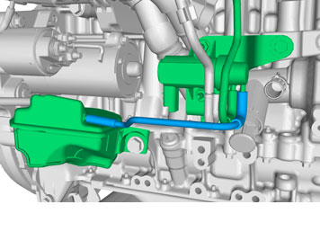
Hose 3
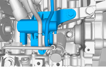
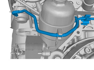
Hose 4
EGR system
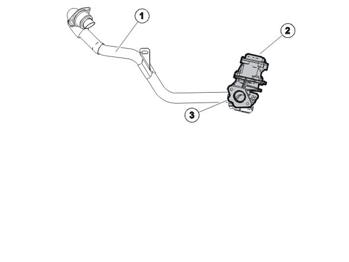
- Connecting pipe to induction manifold
- EGR stepper motor
- EGR valve
The EGR stepper motor is mounted on the cylinder block on the outlet side and controls the amount of exhaust gas returned.
The EGR stepper motor is controlled by the engine control module (ECM) using pulse width modulation.
The catalytic converter is an oxidation catalytic converter that reduces CO and HC emissions.
Its position directly after the turbo, known as CCC (Closed Coupled Catalyst) means that this catalytic converter rapidly reaches the right operating temperature.
Turbocharger
The turbocharger has variable turbine geometry and charge air cooling.
The turbo control valve steplessly controls the underpressure in the pressure box which controls the position of the turbine (Variable Nozzle Turbine, VNT).
The valve can vary the pressure. This also allows the turbo's guide rails to be controlled steplessly, so allowing the desired charge pressure to be attained.
The engine control module (ECM) controls the position of the control valve, and thus also the position of the valve.
Cooling system
Coolant circuit
The flow of coolant is dependent on the following components:
- thermostat
- shutoff valve
- engine temperature sensor
- engine control module (ECM)
The cooling system's primary task is to cool the engine.
The high efficiency of the diesel engine and thus relatively small heat losses, there may be problems with maintaining a comfortable temperature in the cab when the outdoor temperature is low. The job of the various components is, among other things, to work on the basis of the coolant temperature to control the flow of coolant to the heater element in the cab so that the coolant heats up as quickly as possible.
Thermostat housing
WARNING: The engine temperature sensor must not be removed while there is pressure in the cooling system.
The engine's cooling system is fitted with the following in order to ensure rapid heating of the coolant and thus a comfortable temperature in the cab:
- thermostat housing
- electric bypass valve
- electric shutoff valve
The thermostat housing is located on the cylinder head on the gearbox side of the engine.
The engine temperature sensor is located in the thermostat housing and is attached using a clip. The thermostat housing also houses the thermostat and the bypass valve. The thermostat is of conventional type.
The thermostat housing is made of plastic and cannot be taken apart during servicing. The engine temperature sensor can be replaced separately.
For more information on these components, see Design and Function, Engine Control Module (ECM).
Coolant Pump
The coolant pump is located on the engine's belt transmission side and is driven by means of a toothed belt.
Fuel system (diesel)
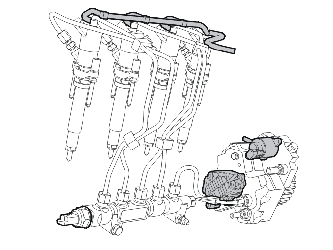
A Bosch Common Rail injection system is used for this engine.
The fuel system (diesel) consists of the following components:
- Fuel filter with fuel preheating
- Fuel pump with integral feed pump and fuel dosing valve
- Pressure pipe
- Distribution pipe
- Fuel pressure sensor on distribution pipe
- Injectors
- Fuel return lines
The fuel filter includes a heater element for use in cold climates. This heater element is switched on automatically.
Fuel pump (diesel)
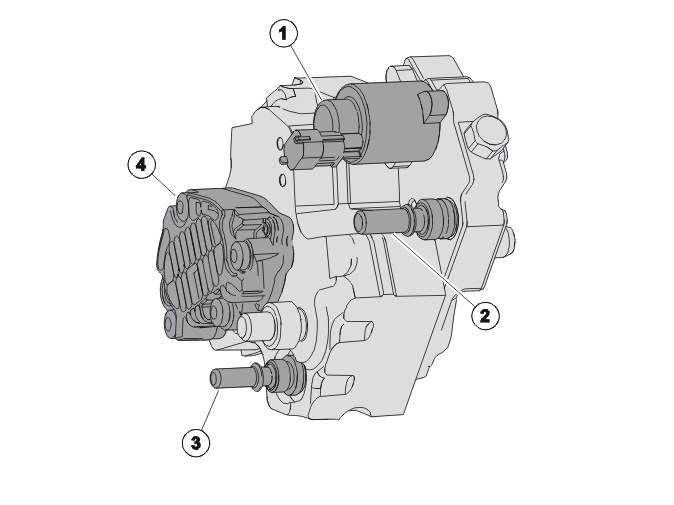
- Fuel dosing valve
- Inflow from fuel filter
- Fuel return
- Feed pump
The fuel dosing valve is located in the inlet channel between the feed pump and the high-pressure pump and meters the quantity of fuel to be fed into the high-pressure chamber according to operating conditions.
The fuel dosing valve has impact protection.
Distribution pipe
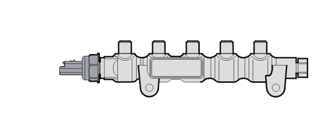
NOTE: The fuel pressure sensor must not be removed from the distribution pipe.
The distribution pipe is attached directly to the cylinder block using 2 retaining screws.
The distribution pipe is made of forged steel. This stores fuel under high pressure and damps pressure fluctuations.
Pressure pipe
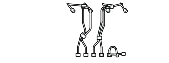
NOTE: The bend radii must not be altered.
NOTE: The pressure pipes must be replaced after being removed so as to prevent leaks.
The pressure pipes connect the distribution pipe to the high-pressure pump and the injectors.
All of the pressure pipes between the distribution pipe and the injectors are of the same length and adapted to fit the fuel system.
Injectors
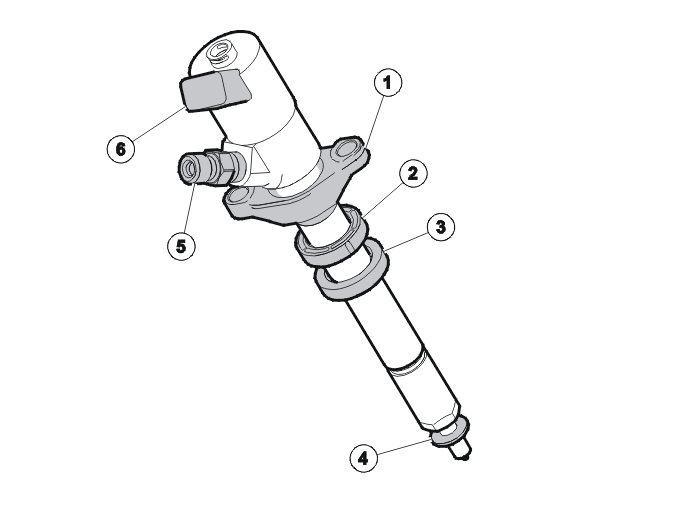
- Retaining ring
- Plastic ring
- Sealing ring
- Copper seal
- Pressure pipe connection
- Connector for line stem
NOTE: Copper seals must not be reused.
Detailed instructions for the correct fitting of the seals and plastic rings are given in the relevant service literature.
The injectors are activated directly by the engine control module (ECM). The injectors are located in retainers attached using 2 nuts each in the valve cover.
The fuel return lines are attached to the top of the injectors using clips. When the injectors are fitted, the pressure pipe connections must point towards the valve cover.
A seal with the valve cover is attained using a sealing ring and a plastic ring positioned in the cylinder head using special tools.
Fuel filter
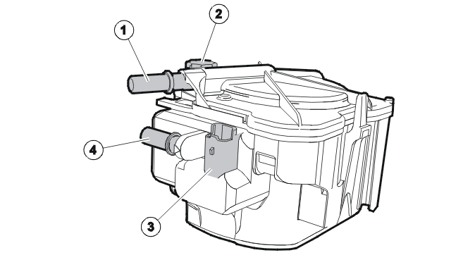
- Outlet to high-pressure pump
- Drain screw
- Electric fuel preheating
- Inflow from fuel tank
The fuel filter is mounted on a retainer directly on the cylinder head and is fitted with electric fuel preheating. The fuel lines are secured using snap-on couplings.
The fuel lines are marked in different colors for the inflow from the tank (white) and the outlet to the high-pressure pump (red).
The water separator must be emptied at regular intervals via the drain screw (2).
The fuel filter has impact protection.
Particle filter system
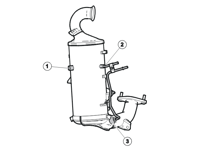
- Connection for the particle filter's exhaust gas temperature sensor
- Pipes to the particle filter's differential pressure sensor
- Particle filter and catalytic converter housing
The exhaust system is fitted with an exhaust gas temperature sensor for the particle filter.
Diesel particles consist of a complex mixture of solids and components in liquid form of varying compositions. Particle filter systems have proven to be an effective way of reducing particle emissions.
The particle filter on the engine is located after the catalytic converter. The catalytic converter and particle filter are located in a combined housing.
The particle filter is honeycomb-shaped. Its walls consist of porous silicon carbide. The individual channels are offset in relation to one another and sealed on one side.
Additive tank
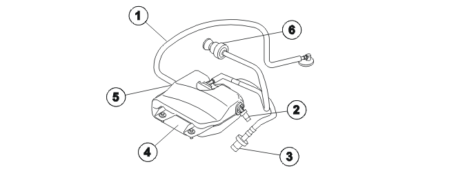
- Fuel line to fuel tank
- Overflow valve (when filling)
- Filler connection
- Additive tank
- Additive pump
- Venting
The additive tank is located behind the fuel tank and is attached to the crossmember. The additive pump consists of one component and is located in the additive tank.
The additive pump and additive tank can only be replaced as a single unit.
The additive tank has a capacity of 1.8 liters and is sufficient for a total distance of 60 000 km. Additive must be topped up as instructed in the service literature.
Additive pump
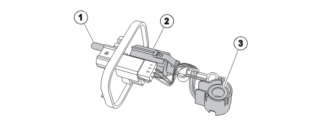
- Connection to fuel tank
- Additive pump
- Piezosensor
The additive pump is a displacement pump (piston pump). It is controlled by the additive dosing module (ADM) and feeds additive via the injector in the fuel tank.
The level in the additive tank is recorded via the piezosensor and transmitted to the additive dosing module (ADM).
Another of its tasks involves recording any change in additive viscosity in relation to the outdoor temperature, correction of the injection time set for the additive then being possible,
Additive
The additive makes sure the particle filter is kept clean. The additive consists of a metallic catalytic substance, cerium and iron. This can accelerate the combustion of carbon particles at lower temperatures.
For more information, see Design and Function, Additive Dosing Module (ADM).
NOTE: As the illustrations in this service information are used for different model years and / or models, some variation may occur. However, the essential information is always correct.
Engine, general
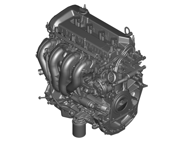
The engine has a variable intake system and an ignition system with directly installed ignition coils. This means that the torque has been increased over the entire rev range at the same time as reducing the fuel consumption.
The engine has mechanical valve lifters and electronic throttle. It has a stepper motor controlled EGR system.
The compact "pent roof" design of the combustion chamber and the V shaped arrangement of the valves provides optimize injection and evacuation. It also provides direct evacuation via the intake passage followed by the combustion chamber (cross-flow) and the exhaust passage. The swirl surfaces of the combustion chamber and the centrally positioned spark plug ensures optimal combustion, low sensitivity to knocking and low, stable exhaust emissions.
It has knock control with knock sensors.
The engine is pendulum mounted on an engine bracket which is secured to the side member. The other mounting bracket is on the transmission and side member.
The sequence for the cylinders starts at the flywheel with cylinder 1.
The bioethanol engine has closer service intervals than the gasoline engine.
The engine has integrated diagnostics for monitoring the exhaust related components. Diagnostics are carried out via the data link connector.
For information on the engine control module (ECM), sensors, and valves, see Design and Function, Engine Control Module (ECM).
Cylinder head and camshafts
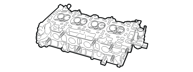
The cylinder block is made from an aluminum alloy. It is reinforced to increase rigidity. The bearing shells are secured by bolts on a separate bridge.
The pistons are made of a light-metal alloy and are graphite covered to reduce friction, noise and vibration.
The exhaust circulation pipes are integrated in the cylinder head.
The water cooled EGR valve is on the side of the cylinder head and is checked by an electric motor.
The bioethanol engine has a new cylinder head with new valve seats on the intake side. These components have a harder surface coating to maintain the service life, as bioethanol (E85) has a corrosive effect.
The exhaust valves lean 10 degrees from vertical. The intake valves lean 19 degrees. The asymmetric layout makes it possible to use larger valve diameters.
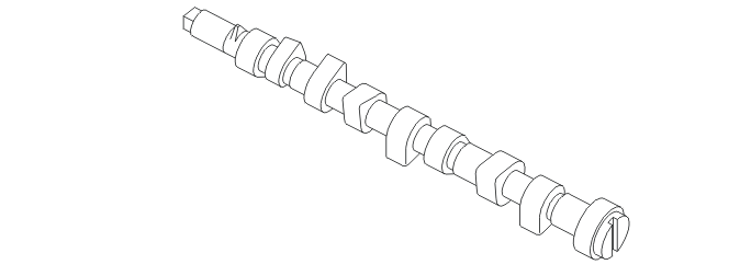
Double overhead camshafts directly affect the valve stem via the valve lifter.
The camshafts are driven by the crankshaft by a chain that has a fixed guide on the slack side and a hydraulic tensioner on the driven side to maintain valve times and reduce noise. There is also a chain with a spring loaded tensioner that drives the oil pump. The system is maintenance free during the service life of the engine. Both the chain guide and the chain tensioner have plastic inserts on the runners to ensure quiet operation.
Camshaft operation
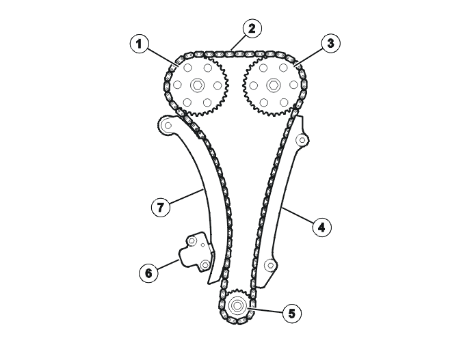
- Exhaust side's camshaft pulley
- Camshaft chain
- Intake side's camshaft pulley
- Chain guide
- Crankshaft pulley
- Hydraulic chain tensioner
- Chain tensioner arm
The engine has chain driven camshafts. The camshaft chain is tensioned by a hydraulic chain tensioner that is supplied with oil from the engine oil circuit.
The double overhead camshafts are driven by the camshaft by a maintenance free chain drive.
The camshaft drive is covered by an aluminum front. The camshaft's oil seal is integrated in the aluminum front, which is installed with the seal.
The valve lifters are made of steel and are mechanical, not hydraulic.
The material in the valve lifters is case-hardened steel. The surfaces between the camshaft and valve are slightly convex to guarantee centered contact.
The camshaft's sprocket is attached by 4 screws in each camshaft.
Intake manifold
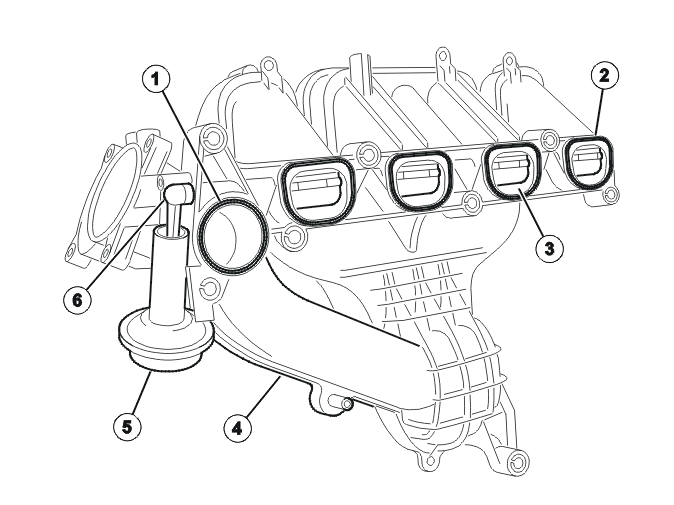
- EGR gasket
- Gasket for intake manifold
- Swirl throttle
- Connection pipes
- Vacuum regulator for swirl damper
- Control arm
The intake pipe consists of three welded shells made of glass fiber polyamide plastic. The base material is mixed with a large proportion of recycled material.
The intake pipe has integrated swirl dampers that reduce the cross-section on the inlet at low speeds. This produces an increased intake of air at low engine speeds.
The increased intake causes the mixture to ignite nearer the spark plug, which means lower fuel consumption and less exhaust gases.
The swirl dampers are adjusted by a vacuum regulator by the intake manifold.
The system is affected by a solenoid. The swirl dampers allow the correct amount of air the pass. When the engine is switched off the swirl dampers are open.
On the upper section of the swirl damper, there is a spring that ensures that the engine receives air even when the swirl damper is fully closed.
The intake manifold is sealed by five rubber gaskets, four for the intake pipes and one for the EGR connection. These must be replaced at service.
The circulating exhaust gases are evenly distributed between the four intake pipes for the fuel rail.
The intake pipe optimizes gas exchange and minimizes the noise level.
The intake pipe is designed for volumetric efficiency at full load and optimal EGR recirculation for all relevant driving conditions.
Crankshaft
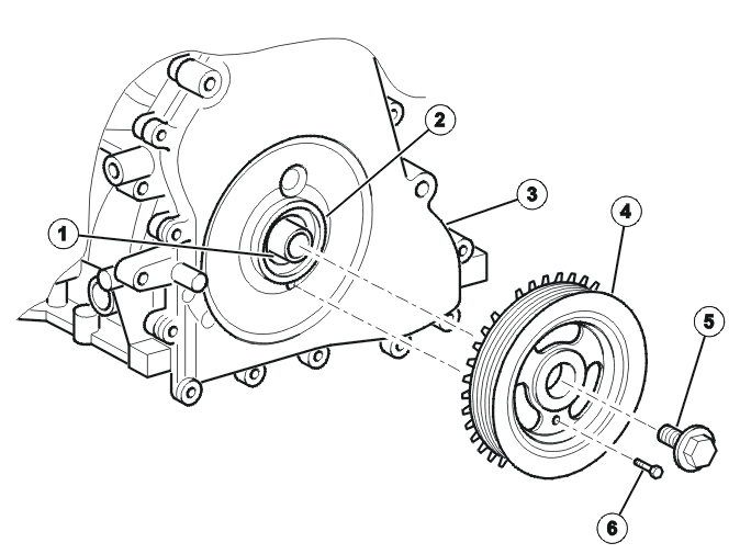
- Crankshaft
- Crankshaft seal
- Front cover
- Vibration damper
- Center screw for the crankshaft
- M6 screw
The crankshaft is made of cast iron. It has five shaft bearings and four counter weights.
The crankshaft's vibration damper is in the same unit as the rotor, which indicates the crankshaft's position. It is secured at the crankshaft by a clamping bolt.
The center screw must be replaced if it is removed. The vibration damper is adjusted into place using an M6 screw. This screw must not be used as a support when tightening the center screw, as this can damage the cam cover.
Connecting rod
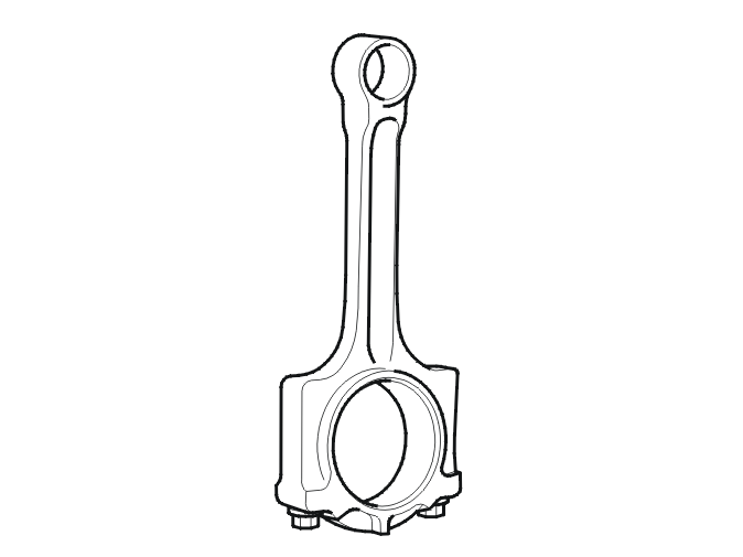
The connecting rod is made of sintered steel. The narrow end is stepped to minimize weight and therefore the mass forces.
The big end is very well dimensioned and does not need dividing into different weight classes.
Piston
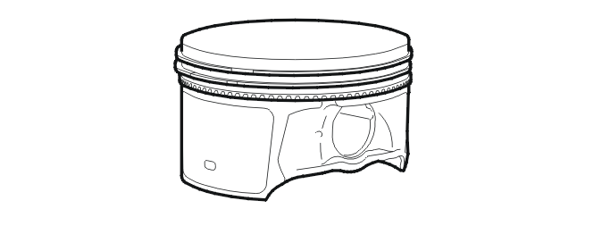
The piston is optimized for low weight. The first oil channel is hard-anodized to reduce wear.
The piston pin is case-hardened and has a conical inner contour to reduce its weight. The piston skirt is covered in graphite to reduce friction and play, which also reduces noise.
The pistons are cooled by oil from the spray nozzles that are integrated in the diaphragm between the main bearings.
Dual mass flywheel
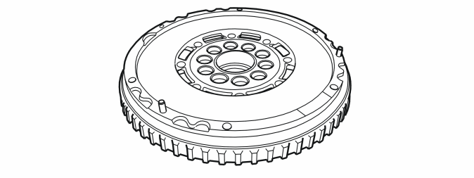
The engine is designed to minimize noise and vibration. The engine is therefore equipped with a dual mass flywheel.
Cylinder head cover
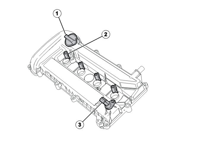
- Oil filler cover
- Mounting for ignition coil
- Camshaft position sensor
The oil filler cover is secured on the valve cover by a bayonet lock.
Cylinder block
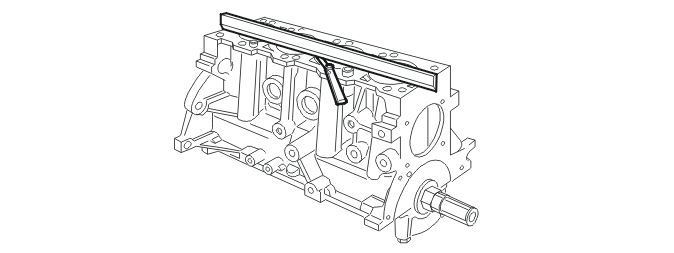
The cylinder block is cast in aluminum alloy. It is designed to increase stability.
The cylinder block has four cast-iron cylinder liners cast in the cylinder block and cannot be replaced.
The oilway and drain plug are cast in the cylinder block.
An aluminum bearing bridge contributes to the high rigidity and provides a stable lower mounting for the clutch cover.
The cylinder walls run down over the crankshaft center to increase rigidity. The cast-iron cylinder sleeves are accurately cast in the aluminum block.
Valve system
The double overhead camshafts have five main thrust bearings and are made of cast-iron.
The cam lobes act directly on the valve stem via mechanical valve lifters.
Shims are not required to adjust valve clearance. Instead, graded valve lifters are already installed during production to achieve the correct valve clearance.
The contact surfaces of the valve lifters are covered in phosphate, which provides better lubrication and minimizes wear.
The valve stem is nitrated to reduce wear.
All components in the valve system are designed with low weight. The valve system is maintenance free during the service life of the engine.
The camshaft profile is optimized for the contact forces between the cam flank and the valve lifters.
Oil pan
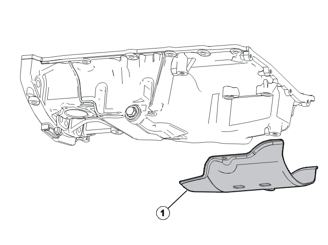
- Protective cover
A protective cover is installed under the A/C compressor.
The oil sump is made of die cast aluminum. The cylinder block and oil sump are optimized for low noise levels and maximum rigidity.
Lubrication system
The oil pump is mounted in the cylinder block and is chain driven via the crankshaft. Nozzles spray oil onto the underneath of the pistons to cool the pistons down.
The oil is led from the oil pan via a suction piece to the oil pump. The oil pump is located on the cylinder block. The oil is then pumped onwards to the oil cooling system and then to the oil filter. The oil flows from the filter through a cast oil duct in the intermediate section to the main bearings. The oil then flows through drilled channels in the crankshaft to the connecting rod bearings.
The camshafts are supplied with oil by a bored channel in the cylinder block. The channel runs through the cylinder head, where it flows out at the bottom of the upper half of the cylinder head. There is a cross duct in the channel to the cylinder head which carries oil to the pistons via a piston cooling valve.
The oil flows onwards via an oil duct to the bearing for the left-hand camshaft and the valve lifters (intake side). The bearings for the right-hand side camshaft (exhaust side) are supplied by a cast cross duct at the front edge of the upper half. Drain holes in the cylinder block release the oil from the cylinder head and crankshaft bearing back to the oil sump.
Oil pump
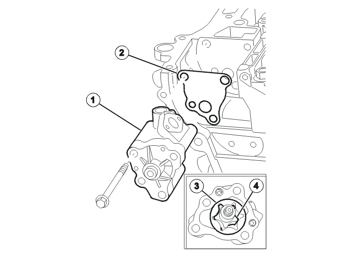
- Oil pump
- Gasket
- Outer rotor
- Inner rotor
The oil pump is of the rotor type. The oil pump lubricates the engine. It runs smoothly and can create the high pressure that is necessary for optimum lubrication.
Oil filter
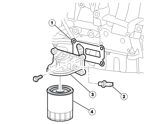
- Gasket
- Oil pressure contact
- Oil filter housing
- Oil filter
The oil filter holder is made of die cast aluminum. It is on the cold side of the engine, on the cylinder block. The oil filter is a metal filter, which is replaced as one unit.
Fuel system
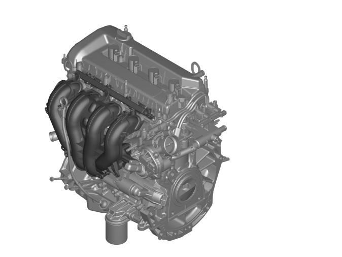
The gasoline engines run on RON 95 fuel.
The bioethanol engine is a flexifuel engine and runs on bioethanol (E85) or RON 95 fuel and all possible mixtures of these two fuels.
The engine is equipped with a non-return fuel system.
Bioethanol engine
The bioethanol engine has a new fuel rail compared to the gasoline engines. The intake pipe has a harder surface coating to maintain the service life, as bioethanol (E85) has a corrosive effect. The valve clearance is slightly less and the injectors have a greater capacity than in the gasoline engine.
Exhaust system
The exhaust system primarily consists of four sections: manifold, three-way catalytic converter (TWC), heated oxygen sensors (HO2S) and muffler. The exhaust system is manufactured from chromium steel sections welded together.
The pipes are specific lengths so that the gases flowing from the cylinders do not interfere with each other and so that there is also good flow distribution in the three way catalytic converter (TWC). There is a boot on the three way catalytic converter (TWC) to absorb engine movements and any manufacturing and installation tolerances.
The entire exhaust system is manufactured in chromium steel. A three-way catalytic converter (TWC) consists of perforated ceramic beads or metal substrates. These are coated with a Wash-coat and then a further coating of the catalytic inert metals, platinum, palladium and rhodium. Heated oxygen sensors (HO2S) are used to control the engine and monitor the three-way catalytic converter (TWC). There is one heated oxygen sensor (HO2S) before and one heated oxygen sensor (HO2S) in the three-way catalytic converter (TWC).
The three-way catalytic converter (TWC) consists of a metal monolith and is located directly on the exhaust manifold. The location halves the heating time during cold starts. This reduces cold emissions.
Exhaust pipe
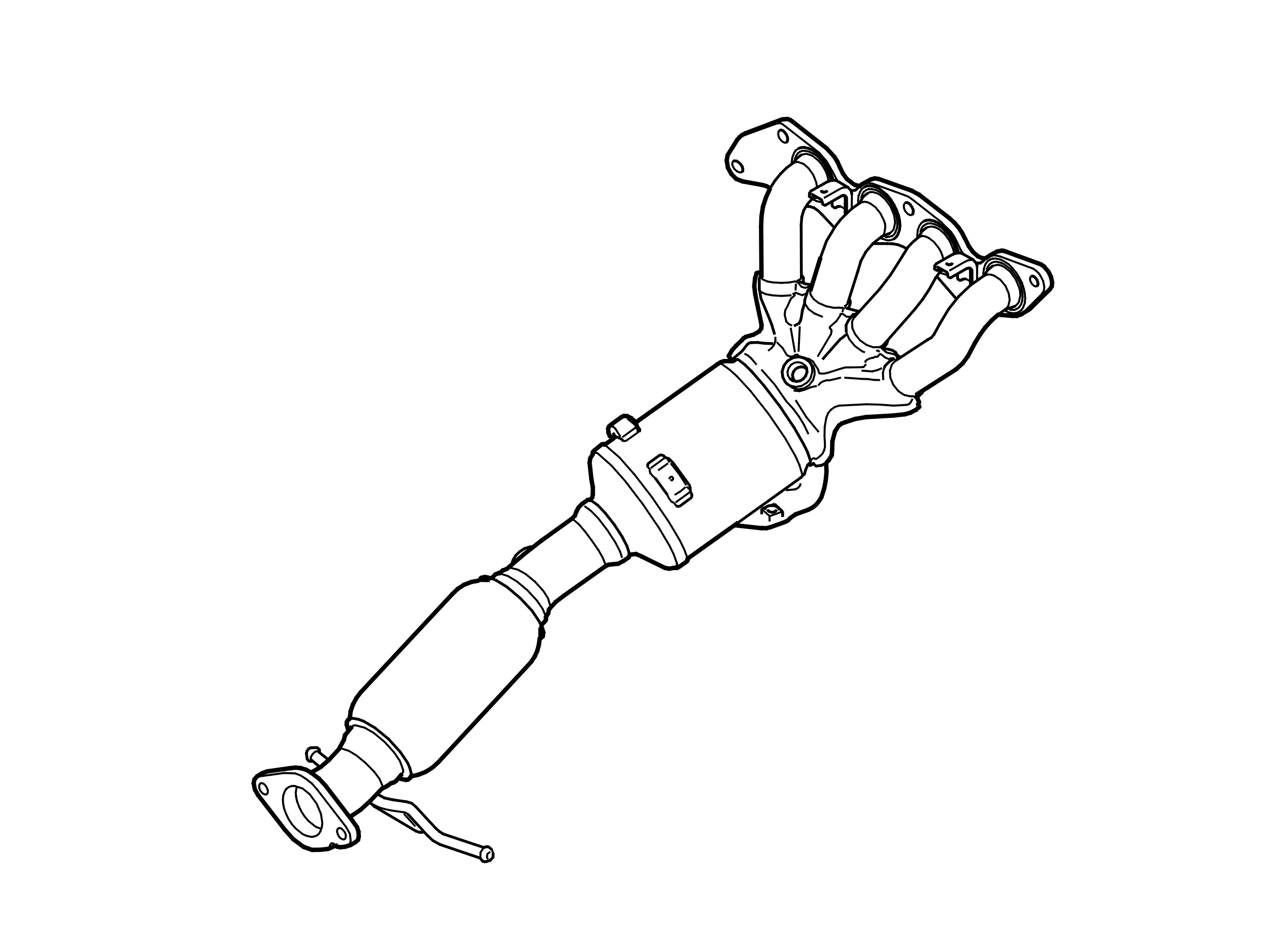
The exhaust pipe is welded stainless steel pipes. Low weight and high heating capacity are achieved by thin pipe walls.
Cooling system
The radiator is made of aluminum to tolerate the thermal variances when the radiator is being both cooled by cool air and heated by hot coolant.
The cooling system is controlled by a mechanical thermostat. The cooling system expands when energy, in the form of heat, is supplied.
The coolant pump pumps coolant through the cylinder block, and also cools the cylinder head, cylinder sleeves, exhaust bridge spark plug wells, intake ducts.
The coolant flows in at the pump and passes through a number of channels before it collects and then flows out to the thermostat housing. If the thermostat housing is closed, the coolant passes via the by-pass channel directly to the coolant pump to then circulate through the cylinder block again.
When the fuel combusts in the vehicle's engine, the result is both mechanical work and excess energy. The excess heat is taken away from the engine via the exhaust gases by convection to the air in the engine compartment and also by transfer to the coolant and engine oil. The cooling system is a closed system.
Thermostat housing
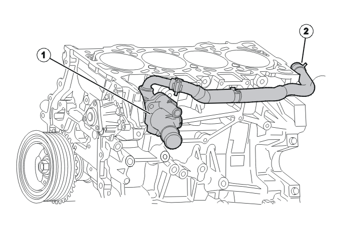
- Thermostat housing
- By-pass hose
The mechanical thermostat allows the engine's cooling temperature to adjust according to the engine's requirements.
Lower cooling temperatures are required at full load. A high cooling temperature is associated with a high oil temperature.
Auxiliaries belt
S40, V50, C30
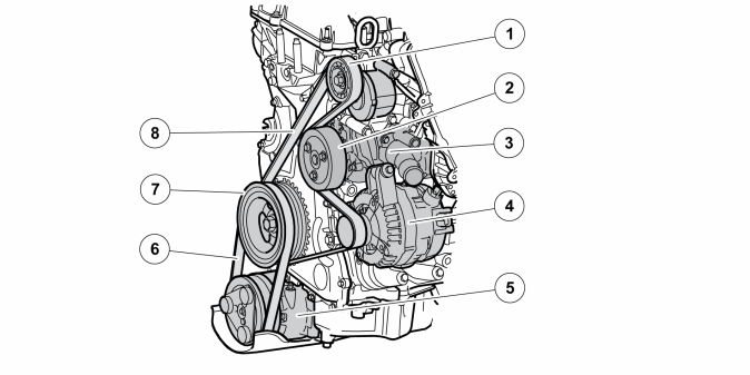
Number | Designation | Number | Designation |
| 1 | Belt tensioner | 5 | Air conditioning (A/C) compressor |
| 2 | Coolant pump | 6 | Elastic Poly V belt |
| 3 | Thermostat housing | 7 | Crankshaft pulley |
| 4 | Generator (GEN) | 8 | Conventional Poly V belt |
The alternator is driven by a separate Poly-V belt and has a mechanical belt tensioner. The coolant pump is also driven by this belt.
The low mounted AC compressor is driven by an elastic Poly-v belt without belt tensioner.
S80 (07-), V70 (08-)
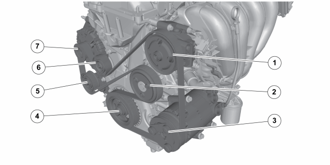
Number | Designation | Number | Designation |
| 1 | Servo pump | 5 | Belt tensioner |
| 2 | Coolant pump | 6 | Guide pulley |
| 3 | Air conditioning (A/C) compressor | 7 | alternator |
| 4 | Crankshaft pulley | – | - |
The generator, AC compressor, servo pump and coolant pump are driven by the crankshaft via a common auxiliaries belt.
Parts & tools for this job For 2004 Volvo S40
- PARTEngine gasket setSearch: Volvo S40 2004 engine gasket set
- TOOLTorque wrenchSearch: 3/8 inch torque wrench
- TOOLFeeler gauge setSearch: feeler gauge set
Links open Amazon search results in a new tab. As an Amazon Associate I earn from qualifying purchases.