
Transmission – Function
- Make
- Volvo
- Model
- V50 Factory Service Manual
- Year
- 2004–2012
- Section
- 09 Miscellaneous › Design and Function › Transmission – Function
Transmission – Function
Clutch, general
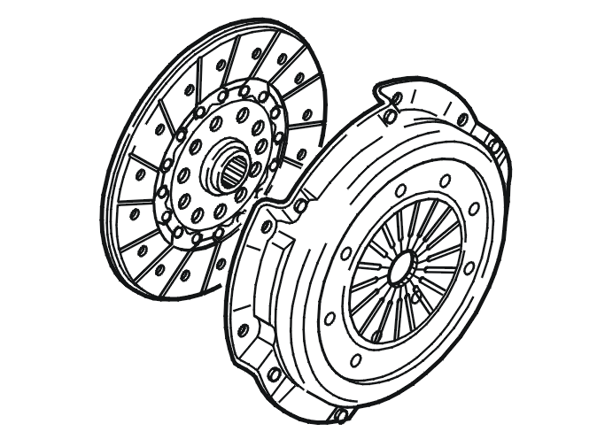
The primary role of the clutch system is to disengage the transmission when shifting, transfer torque and to allow comfortable starting.
Disengagement of the clutch driven plate when shifting is a very important part of this functionality. When the driver presses the clutch pedal, the throwout bearing moves towards the diaphragm spring and disengages the clutch driven plate. The clutch is raised and held in position by the springs riveted to the pressure plate.
The clutch driven plate is trapped between the flywheel and pressure plate to transfer the torque. The torque is transferred via the clutch to the input shaft.
The torque is transferred across the crankshaft via the flywheel to the clutch driven plate. Half of the torque is transferred via the clutch screw to the clutch housing through lifting springs, over to the pressure plate and to the clutch driven plate. The clutch driven plate then transfers the torque via its hub and splines to the input shaft.
Complete disengagement takes place during the last quarter of clutch pedal travel.
During downshifting the rotation speed of the clutch driven plate increases. It decreases during upshifting. The engine speed (RPM) is then synchronized with the vehicle speed when the clutch is released. If there is no disengagement during shifting, there would be abnormal synchronization wear in the transmission.
Pre-tensioned lifting springs connect the clutch housing and the pressure plate.
The clutch is defined by the 3 characteristic curves:
- pressure plate pressure against the clutch driven plate
- diaphragm spring pressure against the throwout bearing
- the lift of the pressure plate.
The pressure of the pressure plate increases as the clutch driven plate wears. This increase in pressure increases the pressure at the diaphragm spring and with it pedal effort as the clutch driven plate wears. The diaphragm spring moves backwards as the clutch driven plate wears. The clutches are guaranteed to tolerate wear of 1.5 mm to the facing. This means that the clutch cover has a wear capacity of 8-9 mm to compensate for rearward movement of the throwout bearing.
An auxiliary spring at the pedal reduces the effort required for disengagement. When the pedal is released, the auxiliary spring is trying to extend, pressing the pedal upwards. As the pedal is pressed and there is little resistance from the clutch, the spring is compressed until the clutch reaches the biting point. The spring then expands as it turns upwards so that it presses down the pedal, minimizing the pedal effort required.
The clutch pedal does not need to be lubricated. All connections in the pedal system are low friction.
Concentric slave cylinder (CSC)
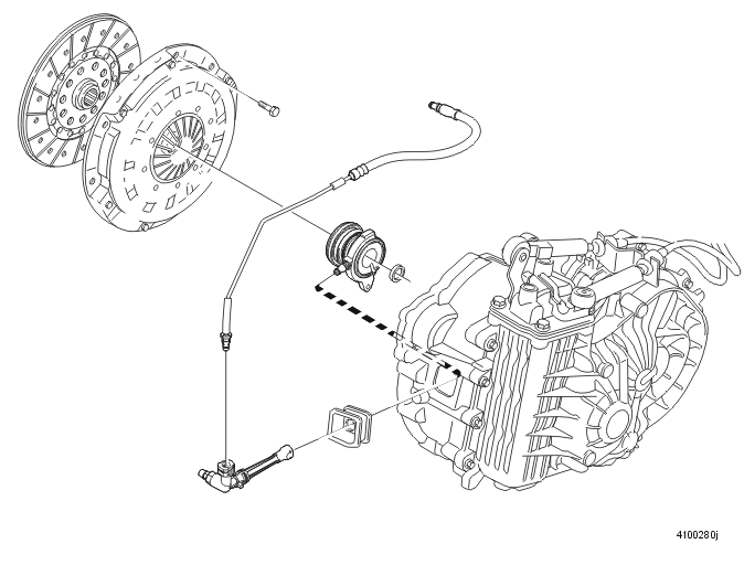
In order to change gears, the transmission must be disengaged from the engine. This is done by the clutch pedal. When the clutch pedal is pressed, fluid is transferred from the master cylinder through a pipe to the concentric slave cylinder (CSC) in the clutch cover. This then acts on the clutch, disengaging the clutch driven plate.
Sound and vibration is also transferred from the engine. The pipe and hose are balanced so that they absorb vibration. On diesel engines, a damping unit is also used. The fluid is encapsulated between two membrane discs which are balanced to the correct rigidity.
Shock load limiter
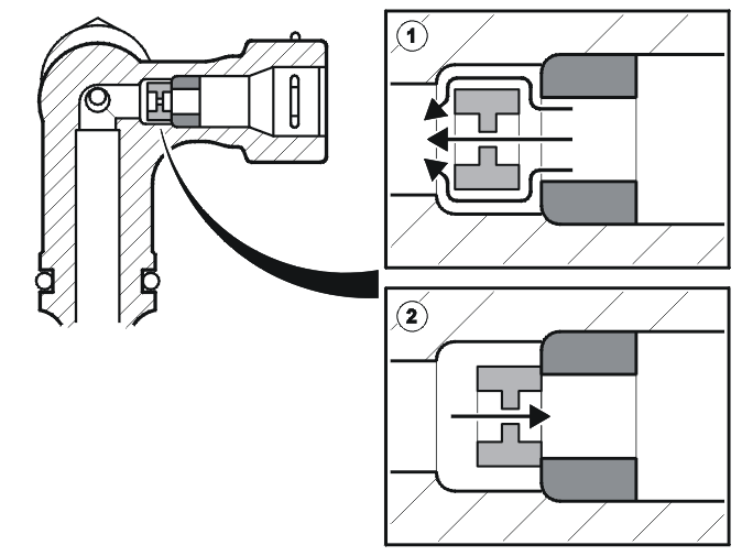
In vehicles which have high torque engines the return time for the clutch may be too short. This means that the torque peak is so high that the drive train could be damaged.
On those occasions where the torque peak is too high, the hydraulic flow is choked by a shock load limiter in the engagement direction between the concentric slave cylinder (CSC) and master cylinder.
Power flow
The torque of the engine is transferred from the clutch to the input shaft and then onwards via different gear sets and driving final drives, depending on the gear selected, to the final drive/differential, drive shafts and out to the front wheels.
1st gear
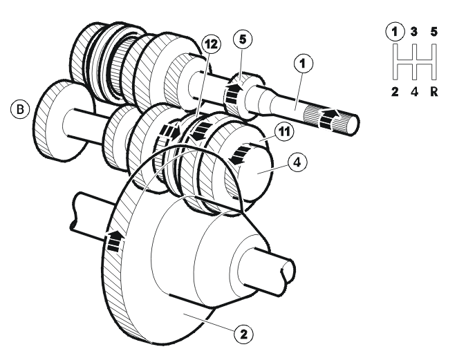
| Number | Designation | Number | Designation |
|---|---|---|---|
| B | Lower output (secondary) shaft | 5 | 1st speed gear |
| 1 | Input shaft | 11 | 1st gear idler wheel /back-up (reverse) intermediate gear |
| 2 | Final drive | 12 | Coupling sleeve for 1st and 2nd gear |
| 4 | Driving final drive |
When 1st gear is selected, the coupling sleeve for 1st-2nd gear is moved by a gear selector fork along the synchronizing hub towards the idler wheel for 1st gear. The coupling sleeve and synchronizing hub lock the idler wheel for 1st gear at the lower output (secondary) shaft.
The engine torque is transferred from the clutch to the input shaft to the gear and idler wheel for 1st gear, through the lower output (secondary) shaft and on to the final drive gear and out to the final drive.
2nd gear
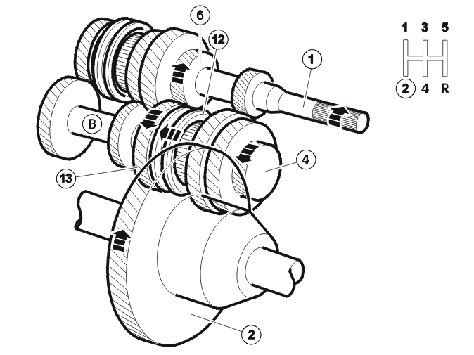
| Number | Designation | Number | Designation |
|---|---|---|---|
| B | Lower output (secondary) shaft | 6 | 2nd speed gear |
| 1 | Input shaft | 12 | Coupling sleeve for 1st and 2nd gear |
| 2 | Final drive | 13 | 2nd gear idler wheel |
| 4 | Driving final drive |
When 2nd gear is selected, the coupling sleeve for 1st-2nd gear is moved by a gear selector fork along the synchronizing hub towards the idler wheel for 2nd gear. The coupling sleeve and synchronizing hub lock the idler wheel for 2nd gear at the lower output (secondary) shaft.
The engine torque is transferred from the clutch to the input shaft to the gear and idler wheel for 2nd gear, through the lower output (secondary) shaft and on to the final drive gear and out to the final drive.
3rd gear
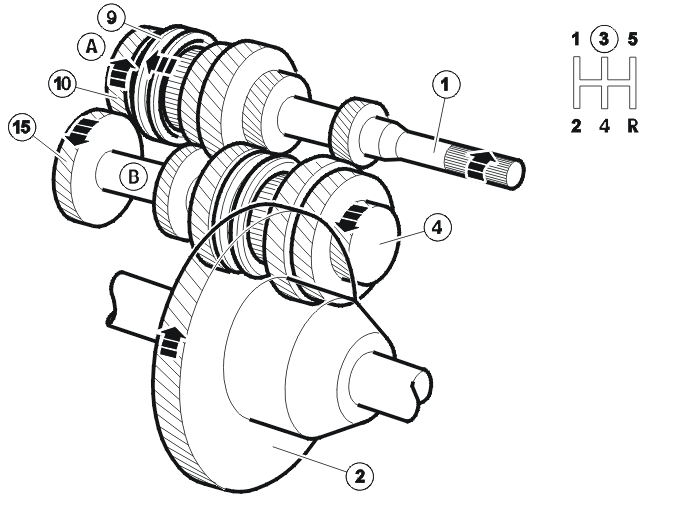
| Number | Designation | Number | Designation |
|---|---|---|---|
| A | Primary shaft | 4 | Driving final drive |
| B | Lower output (secondary) shaft | 9 | Coupling sleeve for 3rd and 4th gear |
| 1 | Input shaft | 10 | 3rd gear idler wheel |
| 2 | Final drive | 15 | 3rd speed gear |
When 3rd gear is selected, the coupling sleeve for 3rd/4th gear is moved by a gear selector fork along the synchronizing hub towards the idler wheel for 3rd gear. The coupling sleeve and synchronizing hub lock the idler wheel for 3rd gear at the primary shaft.
The engine torque is transferred from the clutch to the input shaft, to the idler wheel for 3rd gear. It is then transferred to the gear for 3rd gear on the lower output (secondary) shaft, and on to the final drive gear and out to the final drive.
4th gear
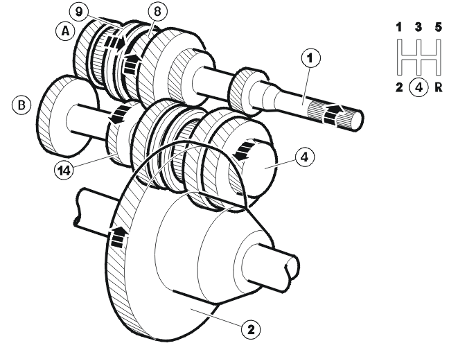
| Number | Designation | Number | Designation |
|---|---|---|---|
| A | Primary shaft | 4 | Driving final drive |
| B | Lower output (secondary) shaft | 8 | 4th gear idler wheel |
| 1 | Input shaft | 9 | Coupling sleeve for 3rd and 4th gear |
| 2 | Final drive | 14 | 4th speed gear |
When 4th gear is selected, the coupling sleeve for 3rd/4th gear is moved by a gear selector fork along the synchronizing hub towards the idler wheel for 4th gear. The coupling sleeve and synchronizing hub lock the idler wheel for 4th gear at the primary shaft.
The engine torque is transferred from the clutch to the input shaft, to the idler wheel for 4th gear. It is then transferred to the gear for 4th gear on the lower output (secondary) shaft, and on to the final drive gear and out to the final drive.
5th gear
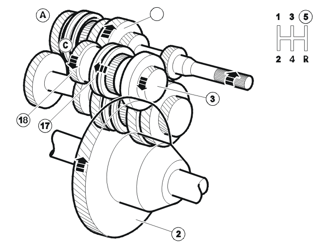
| Number | Designation | Number | Designation |
|---|---|---|---|
| A | Primary shaft | 7 | 5th speed gear |
| C | Upper output (secondary) shaft | 17 | Coupling sleeve for 5th/back-up (reverse) gear |
| 2 | Final drive | 18 | 5th gear idler wheel |
| 3 | Driving final drive |
When 5th gear is selected, the coupling sleeve for 5th/back-up (reverse) gear is moved by a gear selector fork along the synchronizing hub towards the idler wheel for 5th gear. The coupling sleeve and synchronizing hub lock the idler wheel for 5th gear at the upper output (secondary) shaft.
The engine torque is transferred from the clutch to the input shaft, to the gear on the primary shaft for the idler wheel for 5th gear on the upper output (secondary) shaft, and on to the final drive gear and out to the final drive.
Back-up (reverse) gear
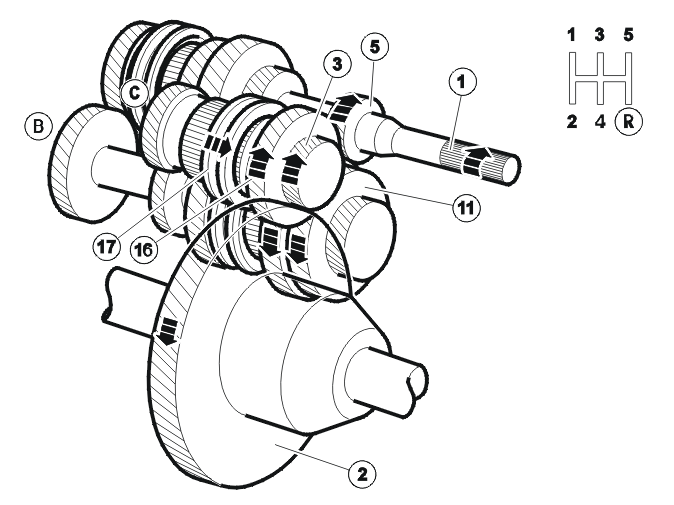
| Number | Designation | Number | Designation |
|---|---|---|---|
| B | Lower output (secondary) shaft | 9 | Coupling sleeve for 3rd and 4th gear |
| C | Upper output (secondary) shaft | 11 | 1st gear idler wheel /back-up (reverse) intermediate gear |
| 1 | Input shaft | 16 | Idler wheel for back-up (reverse) gear |
| 2 | Final drive | 17 | Coupling sleeve for 5th/back-up (reverse) gear |
| 3 | Driving final drive | 20 | Synchronizing relay |
| 5 | 1st speed gear |
When back-up (reverse) gear is selected, the coupling sleeve for 5th/back-up (reverse) gear is moved by a gear selector fork along the synchronizing hub towards the idler wheel for back-up (reverse). The coupling sleeve and synchronizing hub then lock the idler wheel for back-up (reverse) at the upper output (secondary) shaft.
The engine torque is transferred from the clutch to the input shaft, to the gear on the primary shaft for the idler wheel for 1st gear (which also acts as intermediate gear for back-up (reverse) gear) on the lower output (secondary) shaft. It is then transferred to the idler wheel for back-up (reverse) gear on the upper output (secondary) shaft, and on to the final drive gear and out to the final drive.
Because the idler wheel for 1st gear is used as the intermediate gear for back-up (reverse) gear, there is no separate shaft for back-up (reverse) gear.
Shift mechanism
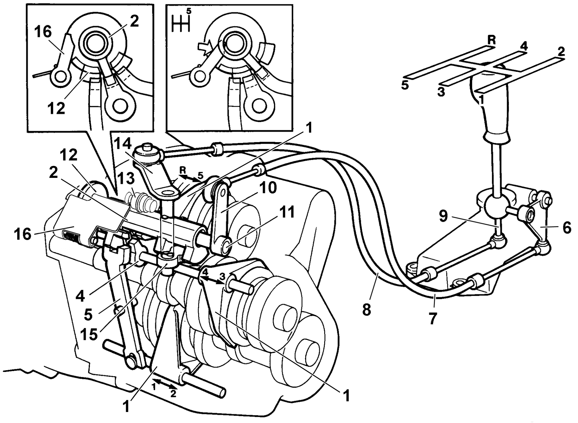
- gear selector fork
- gear selector
- -
- flange
- lever
- link arm
- mechanical cable for lateral movement
- mechanical cable for longitudinal movement
- gear selector lever
- lever for lateral movement
- input gear selector rod
- twist piece
- ball limiter
- lever for longitudinal movement
- selector pin
- spring-loaded back-up (reverse) inhibitor.
The lever for lateral movement is secured to the outside of the input gear selector rod, on which the gear selector and gearshift gate are positioned. The selector pin, which is on the shaft/gear in the transmission housing. It engages and disengages the gears. The shaft/gear and lever are connected to the gear selector lever by mechanical cables.
When the gear selector lever is moved to the side, the outer lever on the gear selector assembly converts this movement to a pulling-sliding movement in the mechanical cable. If the gear selector lever is moved longitudinally however, the second cable is affected directly by the gear selector lever.
The lever for lateral movement acts on the input gear selector rod. At the other end of the gear selector rod there is a spring-loaded neutral return gate. The neutral return gate attempts to engage the neutral position between gears 3rd and 4th gears (when no gear is engaged).
The lever for longitudinal movement is secured to a shaft which is connected to the selector pin. The selector pin acts on the gear selector. The gear selector acts on the flanges and gear selector forks for each gear. These in turn act on the coupling sleeves for the various idler wheels.
When the gear selector lever is moved to the side, the neutral return gate will turn the gear selector to the correct position. When the gear selector lever is moved longitudinally, the gear selector bevel arm and selector pin will act on the gear selector so that the selector fork moves.
Example
When the gear selector lever is moved forwards towards 1st gear, this creates a dragging force in the mechanical cable which turns the lever for longitudinal movement. The gear selector bevel arm will then act on the selector pin and therefore the gear selector so that the lever for 1st and 2nd gear moves in the same direction. The jointed lever then moves the gear selector fork in the opposition direction and engages the synchronizing sleeve with the idler wheel for 1st gear.
When other gears are engaged, this works in a similar way. The gearshift gate then turns the gear selector to the correct position. The gear selector then directly (5th/back-up (reverse) gear) or via another component (other gears) moves the relevant gear selector fork sideways.
Back-up (reverse) inhibitor
There is a spring-loaded back-up (reverse) inhibitor connected to the plate for the gearshift gate which prevents the gear selector lever from moving to back-up (reverse) gear from 5th gear.
The gear selector lever must be moved to neutral before back-up (reverse) gear can be selected. Only then can the gear selector be moved sideways towards back-up (reverse) gear. No separate back-up (reverse) inhibitor is required in the gear selector assembly with this arrangement.
Differential
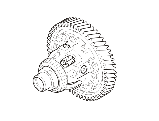
When driving straight ahead, the ring wheel and differential housing rotate at the same speed as the drive shafts and the driving wheels.
When cornering, the differential gears rotate to compensate for the different speeds of the wheels. Because the small side gears are rotating on the shaft journal, the drive shafts can rotate at different speeds. Power is transferred from the differential housing to the drive shafts via the small side gears in the same way as when driving straight ahead. Both drive wheels still have the same driven power.
Mechanical transmission cables
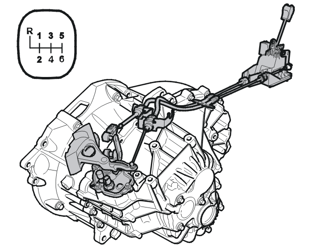
The shift cable:
- is pulled when 1st, 3rd 5th and back-up gears are selected
- is pushed when 2nd, 4th and 6th gears are engaged.
Mechanical transmission cable for lateral travel:
- is pushed when the gear selector lever is moved between 1st and 2nd gears. Gives maximum lateral movement when the lever is moved to back-up gear
- is depressed when the gear selector lever is moved to positions below 5th and 6th gears.
Power flow
1st gear
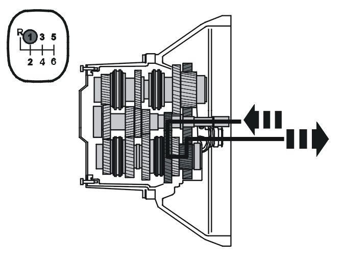
The schematic illustration above displays the power flow.
NOTE: The three shafts are displayed from their actual positions so that their design appears more clear.
When 1st gear is selected, the coupling sleeve for 1st and 2nd gears is moved by a gear selector fork along the synchronizing hub towards the idler wheel for 1st gear. The coupling sleeve and synchronizing hub lock the idler wheel for 1st gear at the lower output (secondary) shaft.
The engine torque is transferred from the clutch via the input shaft to 1st gear and the idler wheel for 1st gear, through the coupling sleeve and via the secondary shaft on to the final drive gear and out to the final drive.
2nd gear
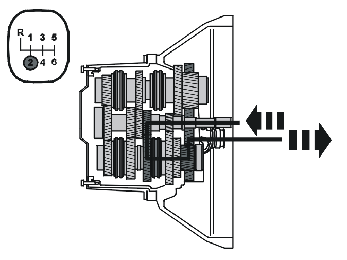
The schematic illustration above displays the power flow.
NOTE: The three shafts are displayed from their actual positions so that their design appears more clear.
When 2nd gear is selected, the coupling sleeve for 1st and 2nd gears is moved by a gear selector fork along the synchronizing hub towards the idler wheel for 2nd gear. The coupling sleeve and synchronizing hub lock the idler wheel for 2nd gear at the lower output (secondary) shaft.
The engine torque is transferred from the clutch via the input shaft to 2nd gear and the idler wheel for 2nd gear, through the coupling sleeve and via the secondary shaft on to the final drive gear and out to the final drive.
3rd gear
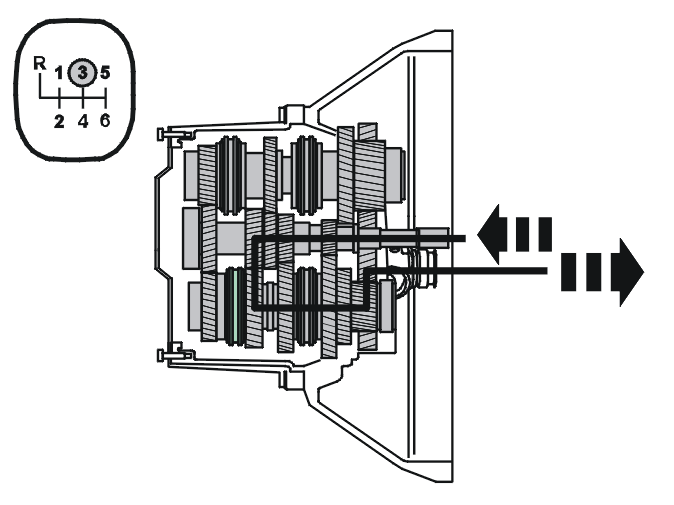
The schematic illustration above displays the power flow.
NOTE: The three shafts are displayed from their actual positions so that their design appears more clear.
When 3rd gear is selected, the coupling sleeve for 3rd and 4th gears is moved by a gear selector fork along the synchronizing hub towards the idler wheel for 3rd gear. The coupling sleeve and synchronizing hub lock the idler wheel for 3rd gear at the primary shaft.
The engine torque is transferred from the clutch via the input shaft, through the coupling sleeve on the primary shaft to the idler wheel for 3rd gear. It is then transferred to the gear for 3rd gear on the lower output (secondary) shaft, and on to the final drive gear and out to the final drive.
4th gear
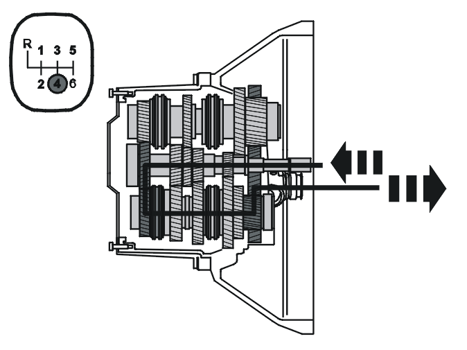
The schematic illustration above displays the power flow.
NOTE: The three shafts are displayed from their actual positions so that their design appears more clear.
When 4th gear is selected, the coupling sleeve for 3rd and 4th gears is moved by a gear selector fork along the synchronizing hub towards the idler wheel for 4th gear. The coupling sleeve and synchronizing hub lock the idler wheel for 4th gear at the primary shaft.
The engine torque is transferred from the clutch via the input shaft, through the coupling sleeve on the primary shaft to the idler wheel for 4th gear. From there it is transferred to the gear wheel for 4th gear on the lower output (secondary) shaft and via the driven gear to the final drive.
5th gear
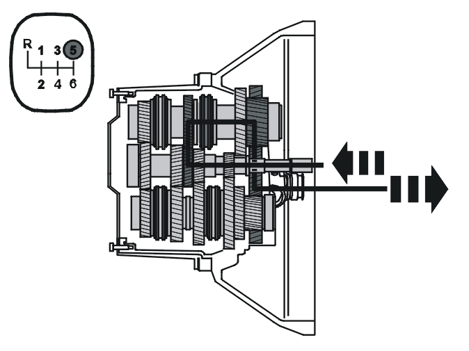
The schematic illustration above displays the power flow.
NOTE: The three shafts are displayed from their actual positions so that their design appears more clear.
When 5th gear is selected, the coupling sleeve for 5th and 6th gears is moved by a gear selector fork along the synchronizing hub towards the idler wheel for 5th gear. The coupling sleeve and synchronizing hub lock the idler wheel for 5th gear at the upper output (secondary) shaft.
The engine torque is transferred from the clutch via the input shaft, to 5th gear on the primary shaft for the idler wheel for 5th gear on the upper secondary shaft, through the coupling sleeve and via the final drive gear and out to the final drive.
6th gear
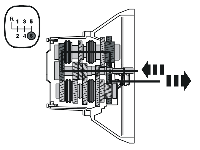
The schematic illustration above displays the power flow.
NOTE: The three shafts are displayed from their actual positions so that their design appears more clear.
The gear wheel for 4th and 6th gears does not only drive the idler wheel for 4th gear but also drives the idler wheel for 6th gear.
When 6th gear is selected, the coupling sleeve for 5th and 6th gears is moved by a gear selector fork along the synchronizing hub towards the idler wheel for 6th gear. The coupling sleeve and synchronizing hub lock the idler wheel for 6th gear at the upper output (secondary) shaft.
The engine torque is transferred from the clutch via the input shaft, to 5th gear on the primary shaft for the idler wheel for 5th gear on the upper secondary shaft, through the coupling sleeve and via the final drive gear and out to the final drive.
Back-up gear
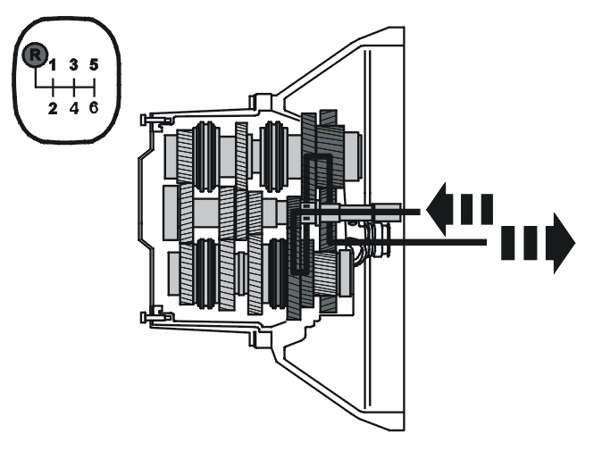
The schematic illustration above displays the power flow.
NOTE: The three shafts are displayed from their actual positions so that their design appears more clear.
When back-up gear is selected, the coupling sleeve for back-up gear is moved by a gear selector fork along the synchronizing hub towards the idler wheel for back-up gear. The coupling sleeve and synchronizing hub lock the idler wheel for back-up gear at the upper secondary shaft.
Engine torque is transferred from the clutch via the input shaft through 1st gear, gear wheel on the primary shaft to the idler wheel of 1st gear, which is used as back-up intermediate gear on the lower secondary shaft. The torque is transferred to the back-up idler wheel on the upper output (secondary) shaft, through the coupling sleeve and via the final drive gear and out to the final drive.
The solution of combining the 1st gear idler wheel and the intermediate gear for back-up means that no separate shaft is required for back up gear. Back up gear is synchronized.
Shifting mechanism
The transfer from the control unit to the selector forks is divided between two locations in the transmission:
- The upper gear selector affects back-up gear and 5th and 6th gears
- The lower gear selector affects 1st, 2nd 3rd, and 4th gears.
Four gear selector forks transfer the movement from the selector unit to the relevant coupling sleeve.
The gear selectors are connected to the gear selector forks which are in the shift unit.
Two carrier plates are used to transfer the torque from the longitudinal movement lever to the axially sliding gear selectors.
The carrier plates move vertically between four possible positions. The different gears can be activated in the different positions.
- In the uppermost position the upper gear selector activates back-up gear
- In the next highest position the lower gear selector activates 1st and 2nd gears
- In the next lowest position the lower gear selector activates 3rd and 4th gears
- In the lowest position the upper gear selector activates 5th and 6th gears.
The longitudinal movement lever affects the gear selector so that the correct gear is engaged. The control unit also contains a spring which helps return the gear selector lever to the neutral position.
Differential
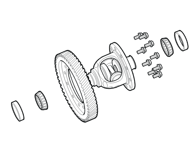
When driving straight ahead, the ring gear and differential housing rotate at the same speed as the drive shafts and the driving wheels.
When cornering, the differential gears rotate to compensate for the different speeds of the wheels. Because the small side gears are rotating on the shaft journal, the drive shafts can rotate at different speeds. Power is transferred from the differential housing to the drive shafts via the small side gears in the same way as when driving straight ahead. Both drive wheels still have the same driven power.
Clutch, general
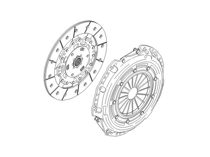
The main tasks of a clutch system are to:
- transfer torque
- disengage during shifting
- provide a comfortable start
- act as an effective shock absorber to eliminate noise and vibration in the chassis and drive train.
Disengagement of the clutch driven plate when shifting is a very important part of this functionality. When the driver presses the clutch pedal, the throwout bearing moves a given distance towards the diaphragm spring and disengages the clutch driven plate. Complete disengagement takes place during the last quarter of clutch pedal travel.
The clutch driven plate is trapped between the flywheel and pressure plate to transfer the torque. The torque is transferred via the clutch to the input shaft.
The torque is transferred across the crankshaft via the flywheel to the clutch driven plate. Half of the torque is transferred via the clutch screw to the clutch housing through lifting springs, over to the pressure plate and to the clutch driven plate. The clutch driven plate then transfers the torque via its hub and splines to the input shaft.
During down-shifting the rotation speed of the clutch driven plate increases. It decreases during up-shifting. The engine speed (RPM) is then synchronized with the vehicle speed when the clutch is released. If there is no disengagement during shifting, there would be abnormal synchronization wear in the transmission.
The clutch is defined by the three characteristic curves:
- pressure plate pressure against the clutch driven plate
- diaphragm spring pressure against the throwout bearing
- the lift of the pressure plate.
The pressure of the pressure plate increases as the clutch driven plate wears. This increase in pressure increases the pressure at the diaphragm spring and with it pedal effort as the clutch driven plate wears. The diaphragm spring moves backwards as the clutch driven plate wears. The clutches are guaranteed to tolerate wear of 1.5 mm to the facing.
Hydraulic clutch control mechanism
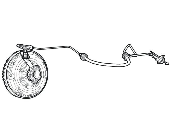
In order to change gears, the transmission must be disengaged from the engine. This is done by the clutch pedal. Fluid is transferred from the master cylinder through a pipe to the slave cylinder by depressing the clutch pedal. This then acts on the clutch, disengaging the clutch driven plate.
Sound and vibration is also transferred from the engine. The pipe and hose are balanced so that they absorb vibration.
Self-adjusting clutch (XTend)

When the facing on a clutch driven plate wears, the normal working position of the pressure plate and the disengagement position increase.
On the self-adjusting clutch an adjuster ring responds to the wear of the clutch driven plate. As wear increases, the adjustment ring moves automatically slightly at the next disengagement and adjusts the bearing position of the diaphragm spring. This means that the operating area of the pressure plate, and therefore engagement pressure, remain constant.
Transmission, general
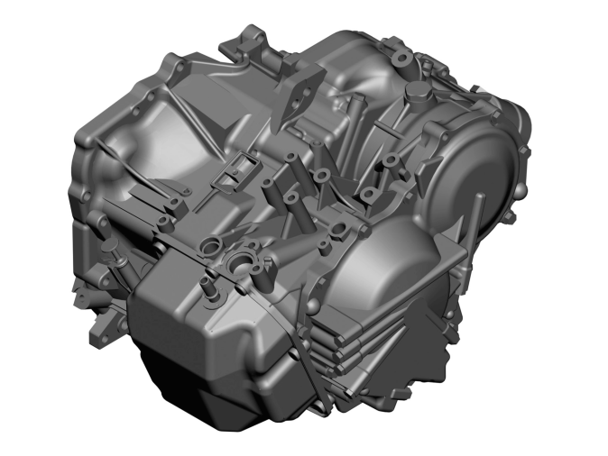
The basic parameters for shifting are the accelerator pedal (AP) position and the vehicle speed.
The gear shift quality is determined by the torque control by reading off speed changes of the transmission input shaft and comparing the calculated value.
This is used to calculate the pressure setting for the clutches and brakes.
Torque converter
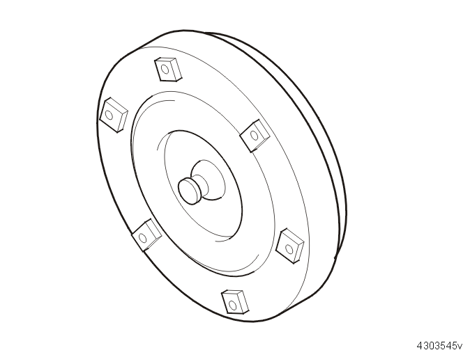
The torque converter functions as an hydraulic automatic clutch. When the engine is idling the pump effect is too weak to drive the turbine and the vehicle will not move. As the engine speed (RPM) rises it successively starts to drive in a gradual way. At higher engine speeds (RPM) the power transfer to the turbine can be up to 95%. The torque converter functions as an hydraulic clutch.
Thanks to a third, smaller wheel, the stator wheel, the torque converter also reinforces the engine torque at low engine speeds.
The rotating impellers and the oil in the torque converter ”slip” slightly and create a slight loss of power, which increases fuel consumption slightly.
Differential
The differential distributes power equally between the drive wheels, even if they are rotating at different speeds.
When driving straight ahead, the ring wheel and differential housing rotate at the same speed as the drive shafts and the driving wheels.
When cornering, the differential gears rotate to compensate for the different speeds of the wheels. Because the small side gears are rotating on the shaft journal, the drive shafts can rotate at different speeds. Power is transferred from the differential housing to the drive shafts via the small side gears in the same way as when driving straight ahead. Both drive wheels still have the same driven power.
Cars with four wheel drive have a splined pin on the differential housing. The sleeve on the pin connects the differential housing with the bevel gear. This transfers the power to the rear wheels.
Gear selector assembly
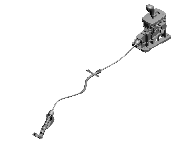
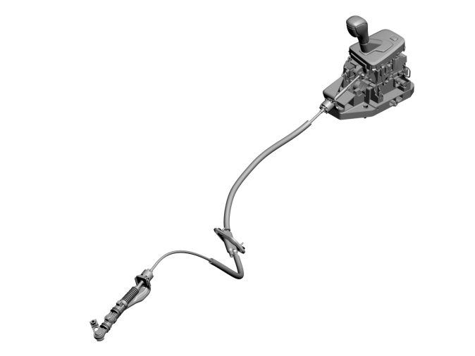
The gear selector assembly is positioned in the center console and is mechanically connected to the transmission by a cable which affects the gear valve.
Gear selectors and cables are shaped differently depending on which car model they are installed in.
Gear selector assemblies with Geartronic, in addition to P/R/N/D modes, also have a manual (M) shifting mode. The manual gear positions can be selected at any point while driving. The engaged gear is locked until the driver selects another gear. The automatic transmission only down shifts if the vehicle slows down to very low speed.
To downshift the gear selector must be moved to minus (-). To upshift the gear selector must be moved to plus (+). At start, 3rd is the highest possible gear.
The engine can only be started in position P or N.
The different gear selector positions
| Position | Meaning | Function |
|---|---|---|
| P | Parking | The output shaft of the transmission is locked, so that the vehicle does not roll. This position should be selected when the vehicle is parked or the engine is started. |
| R | Back-up | Back-up (reverse) gear. This position must only be selected when the vehicle is stationary. |
| N | Neutral | Neutral means that no gear is engaged and the vehicle can roll freely. The engine can be started in this position. |
| D | Drive | The D position is used for all forward motion. When D is engaged the engine drives the vehicle forward. Up and down shifting occurs automatically depending on acceleration and speed. |
| M | Manual | This position allows the driver to change gears manually. |
Power flow
When throttling off, the output shaft's power in 5th, 4th, 3rd, 2nd or reverse gear goes directly to the input shaft without any freewheel, which provides engine braking. 1st gear does not have any engine braking since the power transmission is interrupted by freewheel F2.
Position P (parking)
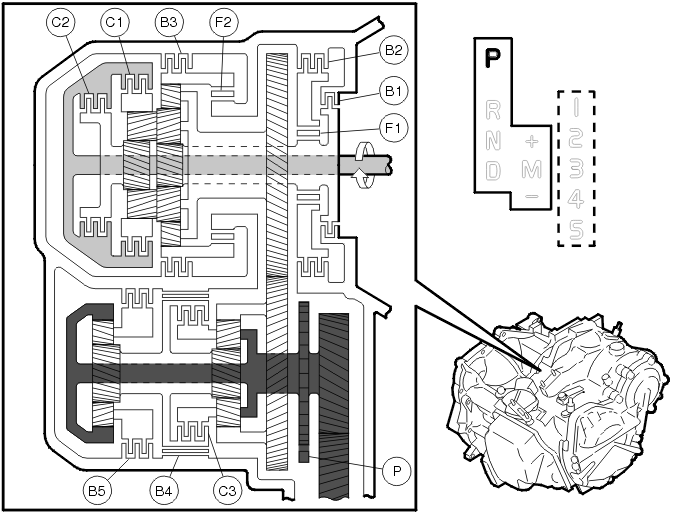
Primary shaft
The input shaft rotates clockwise. All clutches and brakes are disengaged, and no power is transferred to the planetary trains.
Output (secondary) shaft
No power is transmitted to the output (secondary) shaft. Brake band B4locks the sun gear so that it cannot rotate in any direction. Shiftlock P, which is affected by the mechanical link system, is engaged with the lock wheel on the output shaft and prevents the vehicle from rolling.
Position N (neutral)
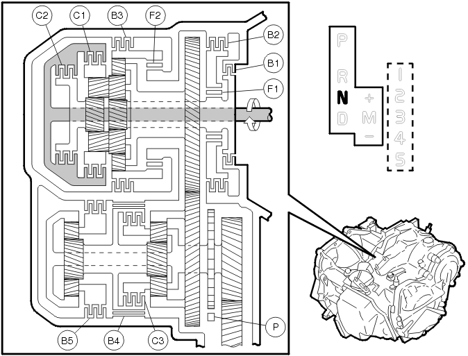
Primary shaft
The input shaft rotates clockwise. All clutches and brakes are disengaged, and no power is transferred to the planetary trains.
Output (secondary) shaft
No power is transmitted to the output (secondary) shaft. Brake band B4 locks the sun gear so that it cannot rotate in any direction. Shift-lock P is disengaged. The planetary gears can rotate freely around the sun gear and the vehicle will start to roll if it is on an incline.
The reason for the brake B4 being activated in both P as N-position is to minimize the engagement shock that otherwise is produced when several brakes and clutches are activated at the same time when the gear selector is moved to D or R-position. Since B4 is still activated in both first gear and reverse, in this way simultaneous engagements are reduced.
Position D (drive) and 1st gear
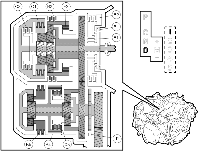
Main section
The input shaft rotates clockwise. Clutch C1 connects the input shaft to the rear ring gear, which rotates clockwise. The rear planetary gear rotates clockwise. The front large planetary gear rotates clockwise with the rear planetary gear as a unit.
The front small planetary gear rotates clockwise. The front ring gear rotates counter-clockwise. Freewheel F2 locks the front ring gear's rotation counter-clockwise.
The front and rear planetary carriers are turned clockwise because of the reactive forces from the small gear. The primary intermediate gear rotates clockwise with the front and rear planetary carriers as a unit.
U/D section
The secondary intermediate gear rotates counter-clockwise. The front ring gear rotates counter-clockwise with secondary intermediate gear as a unit.
The front planetary gear rotates clockwise. The front planetary gear rotates clockwise. The rear sun gear rotates clockwise with the front sun gear as a unit.
The rear planetary gear rotates counter-clockwise. Brake B5 locks the rear planetary carrier's rotation. The rear ring gear rotates counter-clockwise. The front planetary carrier and final drive pinion rotates counter-clockwise with the rear ring gear as a unit. The final drive rotates clockwise.
Engine brake
The primary intermediate gear and front and rear main planetary carriers rotate clockwise. The rear planetary carrier rotates clockwise. The rear planetary gear is turned counter-clockwise while it rotates counter-clockwise because of the resistance from the rear ring gear.
The front large gear wheel is turned clockwise while it rotates counter-clockwise and the small gear wheel is turned clockwise while it rotates clockwise. The front planetary carrier is turned clockwise.
The front ring gear rotates clockwise because the front small gear rotates clockwise, but drive force is reduced because freewheel F2 is disengaged. Therefore the engine brake does not operate.
Position D and 2nd gear
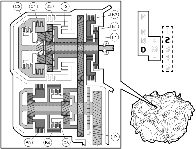
Main section
The input shaft rotates clockwise. Clutch C1 connects the input shaft to the rear ring gear. The rear ring gear rotates clockwise. The rear planetary gear rotates clockwise.
The front large planetary gear rotates clockwise with the rear planetary gear as a unit. Brake B2, freewheel F1 and brake B1 lock the sun gear's rotation.
The front and rear planetary carriers are turned clockwise because of the reactive forces from the front large gear. The primary intermediate gear rotates clockwise with the front and rear planetary carriers as a unit.
U/D section
The secondary intermediate gear rotates counter-clockwise. The front ring gear rotates counter-clockwise with the secondary intermediate gear as a unit. The front planetary gear rotates clockwise. The front planetary gear rotates clockwise.
The rear sun gear rotates clockwise with the front sun gear as a unit. The rear planetary gear rotates counter-clockwise. Brake B5 locks the rear planetary carrier's rotation. The rear ring gear rotates counter-clockwise.
The front planetary carrier and final drive pinion rotates clockwise with the rear ring gear as a unit. The final drive rotates clockwise.
Engine brake
Drive force is transferred directly to the input shaft without the one way clutch. Therefore the engine brake operates.
Position D and 3rd gear
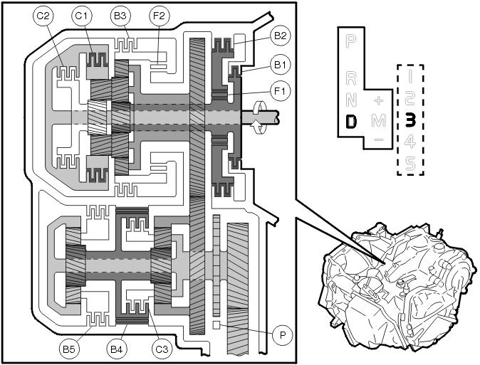
Main section
The input shaft rotates clockwise. Clutch C1 connects the input shaft to the rear ring gear. The rear ring gear rotates clockwise. The rear planetary gear rotates clockwise.
The front large planetary gear rotates clockwise with the rear planetary gear as a unit. Brake B2, freewheel F1 and brake B1 lock the sun gear's rotation.
The front and rear planetary carriers are turned clockwise because of the reactive forces from the front large gear. The primary intermediate gear rotates clockwise with the front and rear planetary carriers as a unit.
U/D section
The secondary intermediate gear rotates counter-clockwise. The front ring gear rotates counter-clockwise with the secondary intermediate gear as a unit. The front planetary gear rotates clockwise. Brake B4 locks the rotation of the front and rear sun gear.
The front planetary carrier is turned clockwise because of the reactive forces from the front large planetary gear. The front planetary carrier and final drive pinion rotate clockwise with the rear ring gear as a unit. The final drive rotates clockwise.
Engine brake
Drive force is transferred directly to the input shaft without the one way clutch. Therefore the engine brake operates
Position D and 4th gear
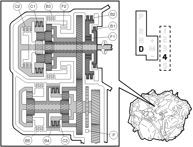
Main section
The input shaft rotates clockwise. Clutch C1 connects the input shaft to the rear ring gear. The rear ring gear rotates clockwise. The rear planetary gear rotates clockwise.
The front large planetary gear rotates clockwise with the rear planetary gear as a unit. Brake B2, freewheel F1 and brake B1 lock the sun gear's rotation.
The front and rear planetary carriers are turned clockwise because of the reactive forces from the front large gear. The primary intermediate gear rotates clockwise with the front and rear planetary carriers as a unit.
U/D section
The secondary intermediate gear rotates clockwise. The front ring gear rotates counter-clockwise with the secondary intermediate gear as a unit. Clutch C3 connects the sun gear to the front planetary carrier.
The front planetary gear cannot rotate and the U/D unit rotates counter-clockwise as a unit. The final drive pinion rotates counter-clockwise with the U/D unit as a unit. The final drive rotates clockwise.
Engine brake
Drive force is transferred directly to the input shaft without the one way clutch. Therefore the engine brake operates.
Position D and 5th gear
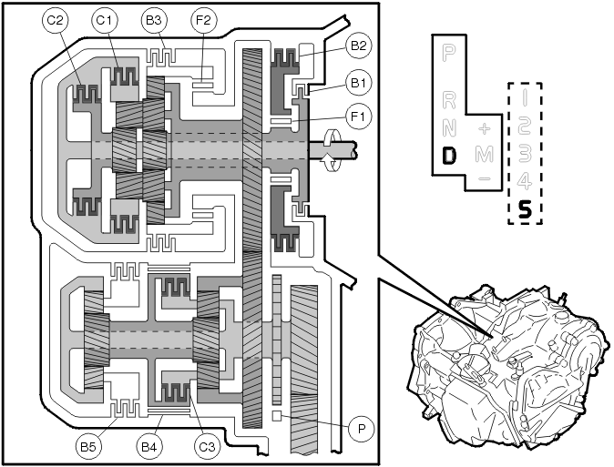
Main section
The input shaft rotates clockwise. Clutch C1 connects the input shaft to the rear ring gear. Clutch C2 connects the input shaft to the sun gear.
The rear planetary gear cannot rotate and the rear planetary gear unit rotates clockwise as a unit. The front planetary gear cannot rotate with the rear planetary gear as a unit. The front planetary unit rotates clockwise as a unit. The primary intermediate gear rotates clockwise with the front planetary unit as a unit.
U/D section
The secondary intermediate gear rotates counter-clockwise. The front ring gear rotates counter-clockwise with the secondary intermediate gear as a unit. Clutch C3 connects the sun gear to the front planetary carrier.
The front planetary gear cannot rotate and the U/D unit rotates counter-clockwise as a unit. The final drive pinion rotates counter-clockwise with the U/D unit as a unit. The final drive rotates clockwise.
Engine brake
Drive force is transferred directly to the input shaft without the one way clutch. Therefore the engine brake operates.
Position R (reverse gear)
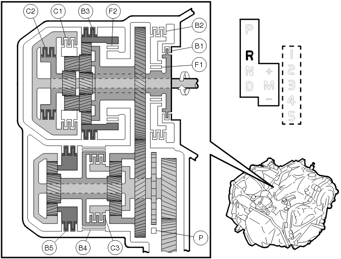
Main section
The input shaft rotates clockwise. Clutch C2 connects the input shaft to the sun gear. The sun gear rotates clockwise.
The rear planetary gear rotates counter-clockwise. The front large planetary gear rotates counter-clockwise with the rear planetary gear as a unit. The front small planetary gear rotates clockwise.
Brake B3 locks the front ring gear's rotation counter-clockwise. The front and rear planetary carriers are turned clockwise because of the reaction forces from the front small gear. The primary intermediate gear rotates counter-clockwise with the front and rear planetary carriers as a unit.
U/D section
The secondary intermediate gear rotates clockwise. The front ring gear rotates clockwise with the secondary intermediate gear as a unit. The front planetary gear rotates clockwise. The front sun gear rotates counter-clockwise.
The rear sun gear rotates counter-clockwise with the front sun gear as a unit. The rear planetary gear rotates clockwise. Brake B5 locks the rear planetary carrier's rotation. The rear ring gear rotates clockwise. The front planetary carrier and final drive pinion rotate clockwise with the rear ring gear as a unit. The final drive rotates counter-clockwise.
Engine brake
Drive force is transferred directly to the input shaft without the one way clutch. Therefore the engine brake operates.
Towing
Towing is only permitted in the vehicle's forward direction at max. 80 km/h for max. 80 km.
The gear selector shall be in position N.
CAUTION: The car must not be towed backwards under any circumstances.
Shift cables
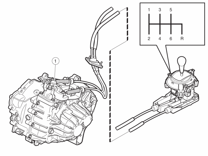
Shift cable:
- pulled when 1st, 3rd and 5th gears are selected
- pushed when 2nd, 4th and 6th gears are engaged.
Mechanical transmission cable for lateral travel:
- pulled when the gear selector lever is moved to the position between 1st and 2nd gears
- pushed when the gear selector lever is moved to the position below 5th and 6th. Gives maximum lateral movement when the lever is moved to back-up (reverse) gear.
There is a return spring on the lateral movement lever. The control unit in the transmission has a return spring.
The mechanical transmission cable for lateral travel is adjustable lengthwise. The adjuster is positioned on the mounting towards the lever on the transmission (1). The spring in the gear selector assembly pulls the mechanical cable and then the mechanical cable is locked by hand using the catch. When locking the gear selector lever and the components in the transmission must be in neutral position.
Power flow
1st gear
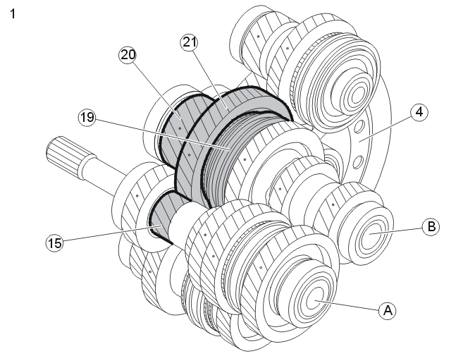
| A | Input shaft |
| B | Intermediate shaft 1-2, 5-6 |
| 4 | Ring gear |
| 15 | 1st gear gear wheel |
| 19 | 1st-2nd gear coupling sleeve |
| 20 | Final drive 1-2, 5-6 |
| 21 | 1st gear idler wheel |
When 1st gear is selected, the coupling sleeve for 1st-2nd gear is moved by a gear selector fork along the synchronizing hub towards the idler wheel for 1st gear. The coupling sleeve and synchronizing hub lock the idler wheel for 1st gear at the intermediate shaft 1-2, 5-6.
Engine torque is transferred to the input shaft via the clutch. The 1st gear rack on the input shaft transfers the power to the idler wheel for 1st gear. From there power is transferred to intermediate shaft 1-2, 5-6 and to the final drive, which in turn transfers the power to the ring gear. The ring gear is connected to the drive shafts through the differential.
2nd gear
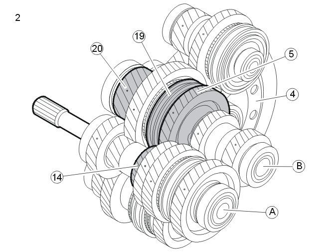
| A | Input shaft |
| B | Intermediate shaft 1-2, 5-6 |
| 4 | Ring gear |
| 5 | 2nd gear idler wheel |
| 14 | 2nd gear gear wheel |
| 19 | 1st-2nd gear coupling sleeve |
| 20 | Final drive 1-2, 5-6 |
When 2nd gear is selected, the coupling sleeve for 1st-2nd gear is moved by a gear selector fork along the synchronizing hub towards the idler wheel for 2nd gear. The coupling sleeve and synchronizing hub lock the idler wheel for 2nd gear at the intermediate shaft 1-2, 5-6.
Engine torque is transferred to the input shaft via the clutch. The 2nd gear rack on the input shaft transfers the power to the idler wheel for 2nd gear. From there power is transferred to intermediate shaft 1-2, 5-6 and to the final drive, which in turn transfers the power to the ring gear. The ring gear is connected to the drive shafts through the differential.
3rd gear
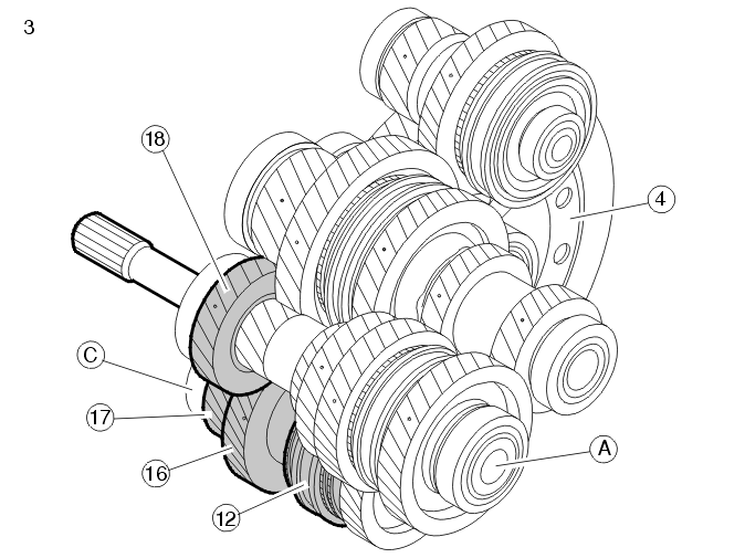
| A | Input shaft |
| C | Intermediate shaft 3-4 |
| 4 | Ring gear |
| 12 | 3rd-4th gear coupling sleeve |
| 16 | 3rd gear idler wheel |
| 17 | Final drive 3-4 |
| 18 | 3rd gear gear wheel |
When 3rd gear is selected, the coupling sleeve for 3rd-4th gear is moved by a gear selector fork along the synchronizing hub towards the idler wheel for 3rd gear. The coupling sleeve and synchronizing hub lock the idler wheel for 3rd gear at the intermediate shaft 3-4.
The torque of the engine is transferred via the clutch to the input shaft. The 3rd gear gearwheel on the input shaft transfers the power to the idler wheel for 3rd gear. From there power is transferred on to intermediate shaft 3-4 and to the final drive which in turn transfers the power to the ring gear. The ring gear is connected to the drive shafts through the differential.
4th gear
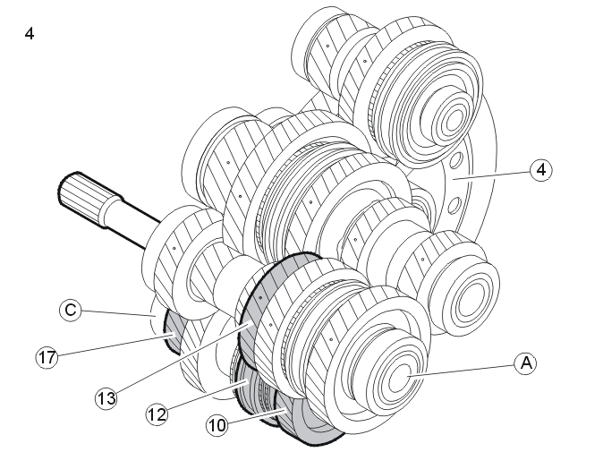
| A | Input shaft |
| C | Intermediate shaft 3-4 |
| 4 | Ring gear |
| 10 | 4th gear idler wheel |
| 12 | 3rd-4th gear coupling sleeve |
| 13 | 4th gear gear wheel |
| 17 | Final drive 3-4 |
When 4th gear is selected, the coupling sleeve for 3rd-4th gear is moved by a gear selector fork along the synchronizing hub towards the idler wheel for 4th gear. The coupling sleeve and synchronizing hub lock the idler wheel for 4th gear at the intermediate shaft 3-4.
The torque of the engine is transferred via the clutch to the input shaft. The 4th gear gearwheel on the input shaft transfers the power to the idler wheel for 4th gear. From there power is transferred on to intermediate shaft 3-4 and to the final drive which in turn transfers the power to the ring gear. The ring gear is connected to the drive shafts through the differential.
5th gear
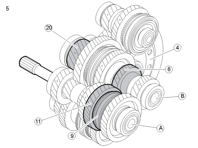
| A | Input shaft |
| B | Intermediate shaft 1-2, 5-6 |
| 4 | Ring gear |
| 6 | 5th gear gear wheel |
| 9 | Coupling sleeve for 5th-6th gear |
| 11 | 5th gear idler wheel |
| 20 | Final drive 1-2, 5-6 |
When 5th gear is selected, the coupling sleeve for 5th-6th gear is moved by a gear selector fork along the synchronizing hub towards the idler wheel for 5th gear. The coupling sleeve and synchronizing hub lock the idler wheel for 5th gear at the input shaft.
The torque of the engine is transferred via the clutch to the input shaft. The 5th-6th coupling sleeve and 5th gear idler wheel, located on the input shaft, transfer the power to the gear wheel for 5th gear. From there power is transferred on to intermediate shaft 1-2, 5-6 and to the final drive which in turn transfers the power to the ring gear. The ring gear is connected to the drive shafts through the differential.
6th gear
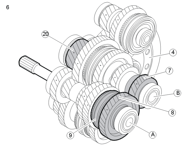
| A | Input shaft |
| B | Intermediate shaft 1-2, 5-6 |
| 4 | Ring gear |
| 7 | 6th gear gear wheel |
| 8 | Idler wheel for 6th gear |
| 9 | Coupling sleeve for 5th-6th gear |
| 20 | Final drive 1-2, 5-6 |
When 6th gear is selected, the coupling sleeve for 5th-6th gear is moved by a gear selector fork along the synchronizing hub towards the idler wheel for 6th gear. The coupling sleeve and synchronizing hub lock the idler wheel for 6th gear at the input shaft.
The torque of the engine is transferred via the clutch to the input shaft. The 5th-6th coupling sleeve and 6th gear idler wheel on the input shaft transfer the power to the gear wheel for 6th gear. From there power is transferred on to intermediate shaft 1-2, 5-6 and to the final drive which in turn transfers the power to the ring gear. The ring gear is connected to the drive shafts through the differential.
Back-up (reverse) gear
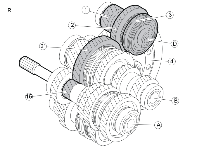
| A | Input shaft |
| B | Intermediate shaft 1-2, 5-6 |
| D | Back-up (reverse) shaft |
| 1 | Final drive for back-up (reverse) gear |
| 2 | Idler wheel for back-up (reversing) gear |
| 3 | Back-up (reversing) gear coupling sleeve |
| 4 | Ring gear |
| 15 | 1st gear gear wheel |
| 21 | 1st gear idler wheel |
When back-up (reverse) gear is selected, the coupling sleeve for back-up (reverse) gear is moved by a gear selector fork along the synchronizing hub towards the idler wheel for back-up (reverse) gear.
The coupling sleeve and synchronizing hub lock the idler wheel for back-up (reverse) gear at the back-up (reverse) shaft.
The torque of the engine is transferred via the clutch to the input shaft. The 1st gear gearwheel on the input shaft transfers the power to the idler wheel for 1st gear. From there to the back-up (reverse) gear idler wheel and then to the coupling sleeve for back-up (reverse) gear. From there power is transferred on to intermediate shaft 1-2, 5-6 and to the final drive which in turn transfers the power to the ring gear. The ring gear is connected to the drive shafts through the differential.
Shift mechanism
The transfer from the control unit to the selector forks is divided between two locations in the transmission:
- The upper gear selector affects back-up (reverse) gear and 1st and 2nd gears
- The lower gear selector affects 3rd, 4th, 5th and 6th gears.
4 gear selector forks transfer the movement from the control to the relevant coupling sleeve.
The shift lever actuates the shift forks, which are mounted in bearings in the housing.
Two carrier plates are used to transfer the torque from the longitudinal movement lever to the axially sliding gear selectors. The carriers run in a groove in the gear selector plate.
The gear selector panel is affected by a carrier plate connected to the lateral movement lever.
The carrier plates move vertically between four possible positions. The different gears can be activated in the different positions.
- In the uppermost position the upper gear selector activates back-up (reverse) gear
- In the next highest position the lower gear selector activates 5th and 6th gears
- In the next lowest position the lower gear selector activates 3rd and 4th gears
- In the lowest position the upper gear selector activates 1st and 2nd gears.
The longitudinal movement lever acts on the shift lever so that the correct gear is engaged. The control unit also contains two springs (10 and 12) that help return the shift lever to the neutral position.
Back-up (reverse) inhibitor
The shift lever assembly houses a solenoid that serves as an electronically controlled reverse inhibitor. If vehicle speed exceeds 25 km/h (15.5 mph), the solenoid is activated and it is not possible to engage reverse gear. When speed drops below 15 km/h (9 mph), the solenoid releases and reverse gear can be engaged.
Differential
When driving straight ahead, the ring wheel and differential housing rotate at the same speed as the drive shafts and the driving wheels.
When cornering, the differential gears rotate to compensate for the different speeds of the wheels. Because the small side gears are rotating on the shaft journal, the drive shafts can rotate at different speeds. Power is transferred from the differential housing to the drive shafts via the small side gears in the same way as when driving straight ahead. Both drive wheels still have the same driven power.
Cars with four wheel drive have a splined pin on the differential housing. The sleeve on the pin connects the differential housing with the bevel gear. Torque is directed from the bevel gear to the rear wheels.
Clutch, general
The primary role of the clutch system is to disengage the transmission when shifting, transfer torque and to allow comfortable starting.
Disengagement of the clutch driven plate when shifting is a very important part of this functionality. When the driver presses the clutch pedal, the throwout bearing moves a given distance towards the diaphragm spring and disengages the clutch driven plate. The clutch is raised and held in position by the springs riveted to the pressure plate.
Complete disengagement takes place during the last quarter of clutch pedal travel.
The clutch driven plate is trapped between the flywheel and pressure plate to transfer the torque. The torque is transferred via the clutch to the input shaft.
The torque is transferred across the crankshaft via the flywheel to the clutch driven plate. Half of the torque is transferred via the clutch screw to the clutch housing through lifting springs, over to the pressure plate and to the clutch driven plate. The clutch driven plate then transfers the torque via its hub and splines to the input shaft.
During down-shifting the rotation speed of the clutch driven plate increases. It decreases during up-shifting. The engine speed (RPM) is then synchronized with the vehicle speed when the clutch is released. If there is no disengagement during shifting, there would be abnormal synchronization wear in the transmission.
Pre-tensioned lifting springs connect the clutch housing and the pressure plate.
The clutch is defined by the 3 characteristic curves:
- pressure plate pressure against the clutch driven plate
- diaphragm spring pressure against the throwout bearing
- the lift of the pressure plate.
The pressure of the pressure plate increases as the clutch driven plate wears. This increase in pressure increases the pressure at the diaphragm spring and with it pedal effort as the clutch driven plate wears. The diaphragm spring moves backwards as the clutch driven plate wears. The clutches are guaranteed to tolerate wear of 1.5 mm to the facing. This means that the clutch cover has a wear capacity of 8-9 mm to compensate for rearward movement of the throwout bearing.
Hydraulic clutch control mechanism with concentric slave cylinder (CSC)
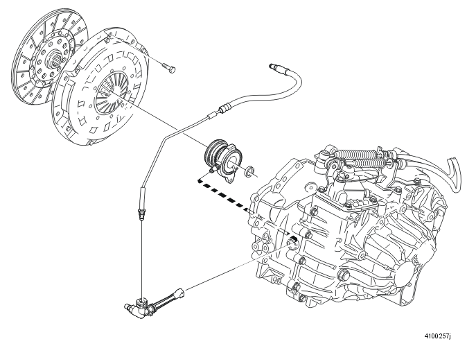
In order to change gears, the transmission must be disengaged from the engine. This is done by the clutch pedal. When the clutch pedal is pressed, fluid is transferred from the master cylinder through a pipe to the concentric slave cylinder (CSC) in the clutch cover. This then acts on the clutch, disengaging the clutch driven plate.
Sound and vibration is also transferred from the engine. The pipe and hose are balanced so that they absorb vibration. On diesel engines, a damping unit is also used. The fluid is encapsulated between two membrane discs which are balanced to the correct rigidity.
Self-adjusting clutch (SAC)
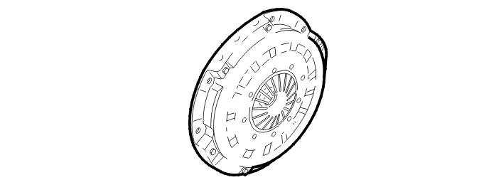
When the facing on a clutch driven plate wears, the normal working position (travel) of the pressure plate and the disengagement position increase.
On the self-adjusting clutch an adjuster ring responds to the wear of the clutch driven plate. As wear increases, the adjustment ring moves automatically slightly at the next disengagement and adjusts the bearing position of the diaphragm spring. This means that the operating travel of the pressure plate and therefore engagement pressure remain constant.
Clutch, general
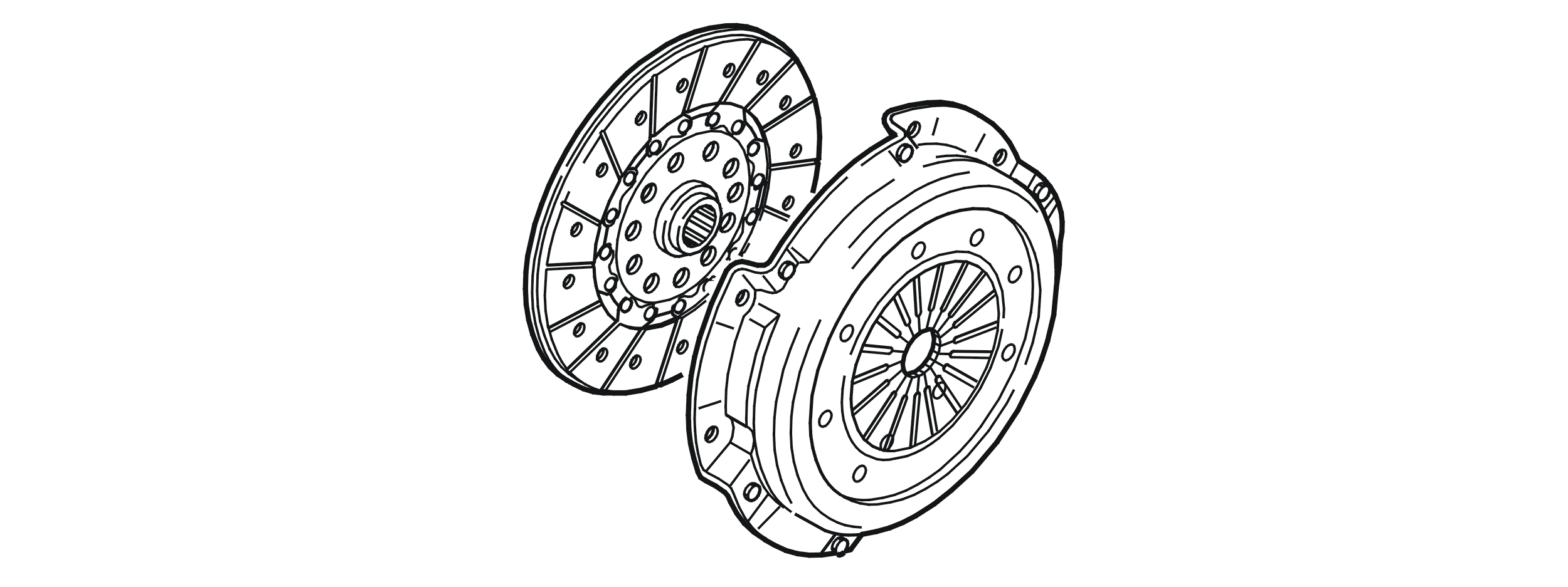
The main tasks of the clutch system are disengagement during shifting, torque transfer and making a comfortable start possible.
Disengaging the clutch plate during shifting is an important part of the functionality. When the driver depresses the clutch pedal, the release bearing moves toward the fan a specific distance and releases the plate. The lift in the clutch is received by the lifting springs, which are riveted to the pressure plate and hold it in place.
Complete disengagement does not occur until the last quarter of clutch pedal travel.
The plate is pinched between the flywheel and pressure plate in order to transfer torque. Torque is transferred to the input shaft via the clutch.
Torque goes across the crankshaft via the flywheel to the clutch plate. Half of the torque is led via the clutch screw across the clutch housing through the lifting spring over to the pressure plate and on to the clutch plate. The clutch plate then transfers the torque via the clutch plate hub and spline to the input shaft.
During shift manoeuvres, the clutch plate speed is increased (when downshifting) or decreased (when upshifting). Engine speed is then synchronised with vehicle speed when the clutch is released. If there were no disengagement when shifting, there would be abnormal wear on the synchroniser ring in the gearbox.
Pretensioned lifting springs connect the clutch housing and the pressure plate.
The clutch is defined by 3 characteristic forces:
- pressure plate force on the clutch plate
- fan force on the release bearing
- pressure plate lift.
Pressure plate force increases as the clutch plate is subjected to wear. Due to this increase in force, fan force and thereby pedal force increase in conjunction with increased wear on the clutch plate. The fan position moves rearward in a degree corresponding to clutch plate wear and the gear ratio in the clutch. The clutch is designed to handle 1.5 mm of lining wear. This means that the clutch cover has an 8-9 mm wear capacity for rearward release bearing movement.
An auxiliary spring at the pedal reduces the amount of force required for disengagement. When the pedal is in its upper position, the auxiliary spring works to expand, which presses the pedal upward. When the pedal starts to be pushed down and the resistance from the clutch is small, the spring compresses at first by the pedal force until it has reached its breakpoint. It then expands while turning upward, thus helping to press the pedal down, which makes the clutch easier to depress.
The clutch pedal requires no lubrication. All joints of the pedal system are low-friction.
Concentric slave cylinder
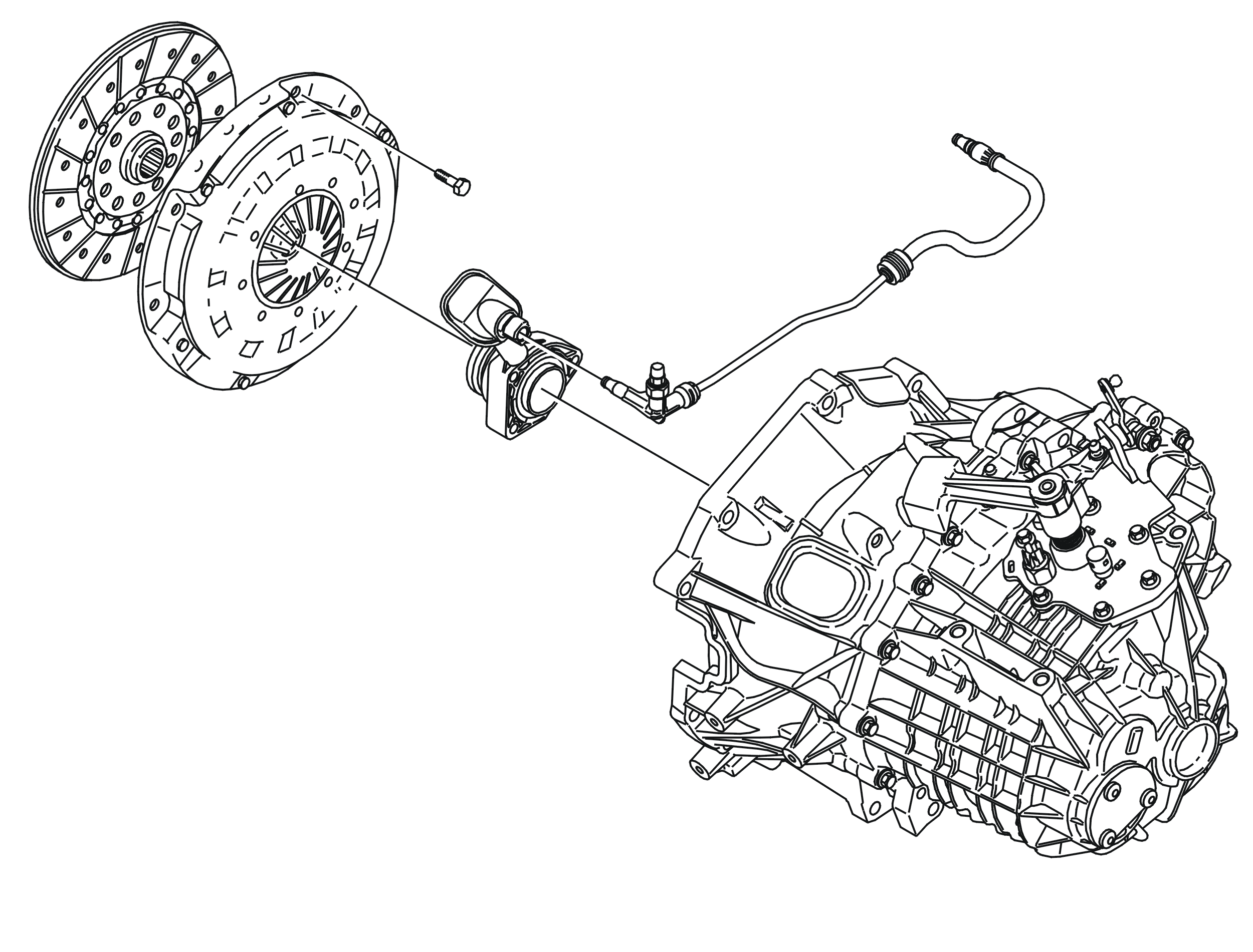
In order to shift, the gearbox must be disengaged from the engine, which is done with the clutch pedal. When the clutch pedal is depressed, fluid is transferred through pipes from the master cylinder to the slave cylinder housed in the clutch cover. This then presses on the clutch, which releases the clutch plate. Noise and vibrations are also sent from the engine. To reduce this, the pipe and hose are designed to absorb vibration. Diesel-engined vehicles also employ a damping unit, a volume of fluid enclosed between two membrane discs that are adjusted to the correct degree of rigidity.
Self-adjusting clutch (XTend) (D4164T only)
When the lining on a clutch plate is worn, the normal work position of the pressure plate changes and disengagement pressure increases.
On the self-adjusting clutch, an adjuster ring is affected by clutch plate wear. If there is wear, the adjuster ring automatically moves a bit during the next disengagement and adjusts the bearing point of the fan. This keeps the work area of the pressure plate and thereby the disengagement pressure constant.
The path of the force
Engine torque is transferred from the clutch to the gearbox input shaft and then onward via various drive gear sets and driving final drive pinion, depending on which gear is engaged, to the final drive/differential, drive shafts and out to the front wheels.
1st gear
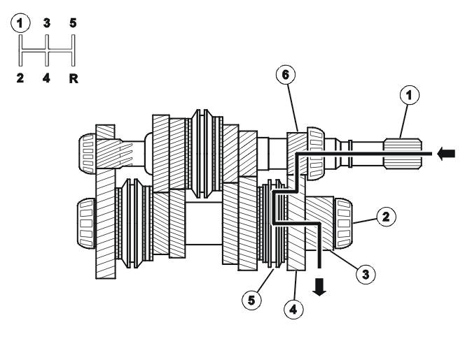
- Input shaft
- Output shaft
- Final drive rack
- 1st gear impeller
- 1st and 2nd gear synchronisation
- 1st gear rack
2nd gear
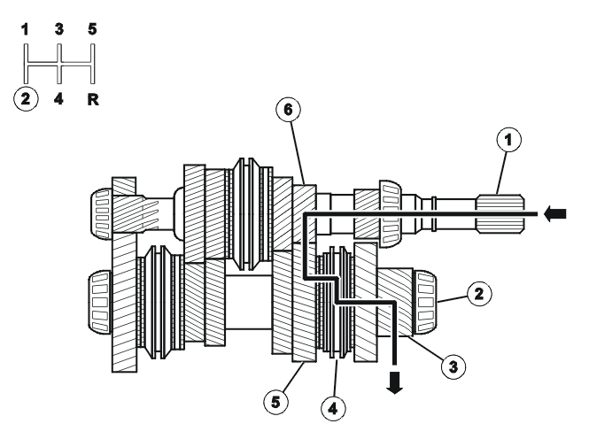
- Input shaft
- Output shaft
- Final drive rack
- 1st and 2nd gear synchronisation
- 2nd gear impeller
- 2nd gear rack
3rd gear
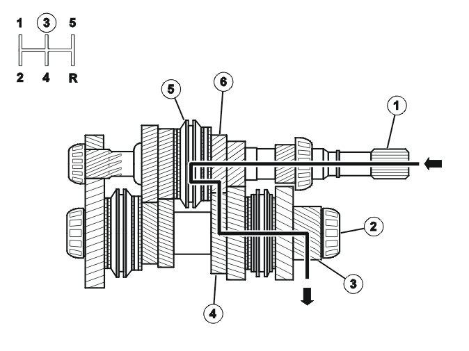
- Input shaft
- Output shaft
- Final drive rack
- 3rd gear gearwheel
- 3rd and 4th gear synchronisation
- 3rd gear impeller
4th gear
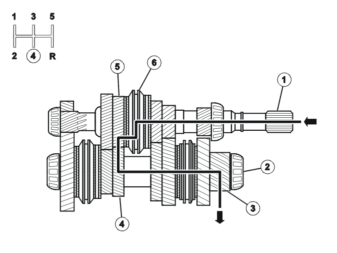
- Input shaft
- Output shaft
- Final drive rack
- 4th gear gearwheel
- 4th gear impeller
- 3rd and 4th gear synchronisation
5th gear
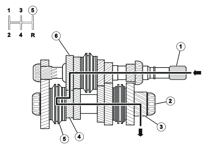
- Input shaft
- Output shaft
- Final drive rack
- 5th gear impeller
- 5th and reverse gear synchronisation
- 5th gear gearwheel
Reverse gear
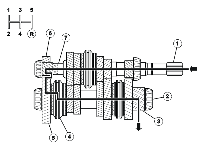
- Input shaft
- Output shaft
- Final drive rack
- 5th and reverse gear synchronisation
- Reverse gear impeller
- Reverse intermediate gear
- Reverse gear rack
Shift mechanism
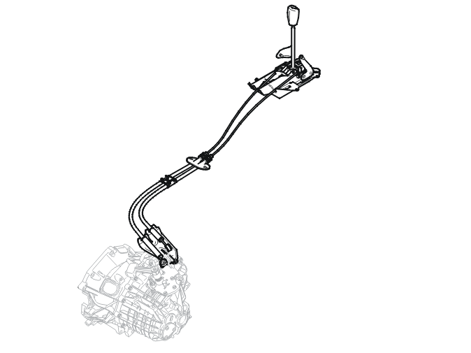
When the gear level is moved laterally toward the 1st gear position, a pressing force is exerted on the cable that turns the lever for lateral travel.
When the gear lever is moved forward toward the 1st gear position, a pressing force is exerted on the cable that turns the lever for longitudinal travel.
This is executed in a similar manner when other gears are engaged.
Differential
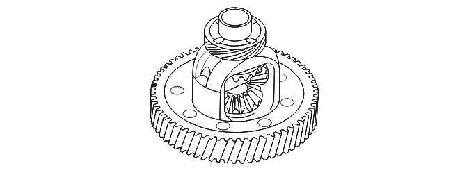
The differential distributes the force between the drive wheels.
Torque is transferred from the ring gear to the two conical differential pinions on the differential shaft and then on to the conical gearwheels on the drive shafts. When taking curves, the drive wheels need to move at different speeds since the wheels are moving different distances. This is made possible by the differential gears that rotate on their own shaft.
Parts & tools for this job For 2004 Volvo V50
- TOOLTorque wrenchSearch: 3/8 inch torque wrench
- TOOLSocket setSearch: socket set metric
- BOOKHaynes manualSearch: Haynes manual Volvo V50
Links open Amazon search results in a new tab. As an Amazon Associate I earn from qualifying purchases.