
V70 2.4 L5-2.4L VIN 61 B5244S (2001)
Electronic Throttle Actuator: Description and Operation
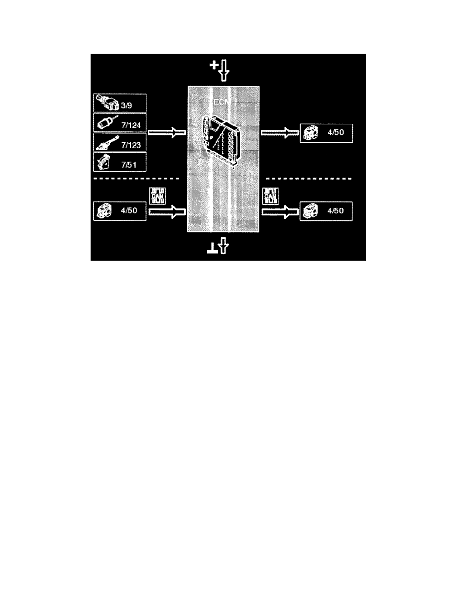
Electronically control led throttle system
In addition to the engine control module (ECM), the electronically controlled throttle system consists of an electronic throttle module (ETM) and an
accelerator pedal (AP) position sensor. The system does not have a mechanical link system or mechanical cable. The accelerator pedal (AP) position
sensor generates two output signals: An analog signal which is approximately 0.5 V when idling and approximately 4.5 V at wide open throttle
(WOT). There is also a pulse width modulated digital signal.
The engine control module (ECM) uses the input signal from the accelerator pedal (AP) position sensor to calculate the requested position of the
throttle. The calculated signal, which corresponds to the requested air flow, is transmitted to the electronic throttle module (ETM) on the high-speed
side of the Controller area network (CAN). The electronic throttle module (ETM) receives the signal and deploys the shutter in the module to the
requested position. The electronic throttle module (ETM) transmits a signal (which corresponds to the actual position of the throttle) on the high speed
side of the controller area network (CAN) back to the engine control module (ECM) to confirm that the electronic throttle module (ETM) has opened
the throttle as requested.
Both the engine control module (ECM) and electronic throttle module (ETM) contain a micro-processor which controls the throttle based on requests
from the engine control module (ECM). The micro-processors also diagnose and monitor their own and each other's function. When there is a fault,
the micro-processors transmit a message to the driver information module (DIM) via the Controller area network (CAN) requesting that the emissions
warning lamp lights. The electronic throttle module (ETM) consists of a damper motor and a throttle disc amongst other components. The throttle disc
is mechanically connected to two potentiometers, which are mounted at each end of the throttle spindle.
The damper motor is supplied with 12 V and both potentiometers with 5 V.
For safety reasons, two potentiometers transmit the same signal about the position of the throttle to the electronic throttle module (ETM).
If the signal from one of the potentiometers is missing or faulty, the electronic throttle module (ETM) is still able to calculate the position of the
throttle using the signal from the other potentiometer. This maintains the drivability of the car. However the throttle system will be in Limp-home
mode and may react differently than normal.
At closed throttle position (CTP) the signal is approximately 0.1 V and at wide open throttle (WOT) it is approximately 4.8 V.
All signals between the engine control module (ECM) and the electronic throttle module (ETM) are transmitted via the Controller area network
(CAN). A back-up signal is transmitted via a directly connected signal cable between the accelerator pedal (AP) position sensor and the electronic
throttle module (ETM). However the cable runs via the engine control module (ECM).
A simple way to check that the electronic throttle module (ETM) is supplied with power is to switch on the ignition. Power is being supplied if the
electronic throttle module (ETM) beeps. In addition there may be a clicking sound when the throttle disc is calibrated to the mechanical limit position.
The electronically controlled throttle system can be diagnosed by both the engine control module (ECM) and the electronic throttle module (ETM).