
A3 Mk1
| Dismantling and assembling gearbox housing cover, gearbox housing, selector mechanism, input shaft, output shaft (pinion shaft), differential and selector forks |
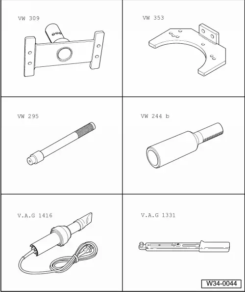
| Special tools and workshop equipment required |
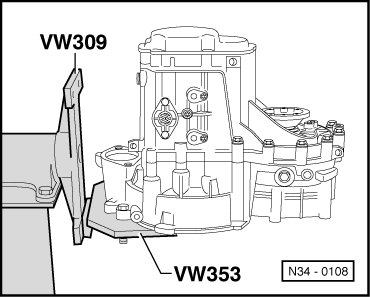
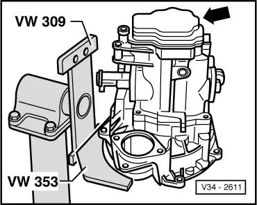
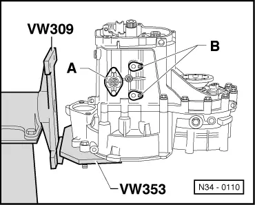
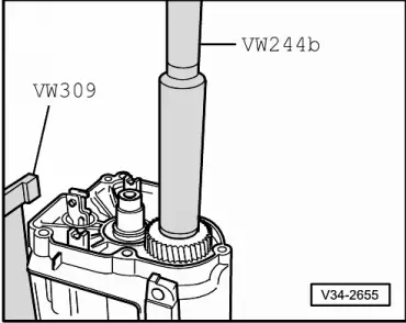
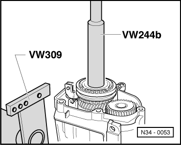
| t | Support plate -VW 309- |
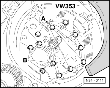
| t | Gearbox support -VW 353- |
| t | Drift -VW 295- |
| t | Drift sleeve -VW 244 B- |
| t | Hot air blower -V.A.G 1416- |
| t | Torque wrench -V.A.G 1331- |
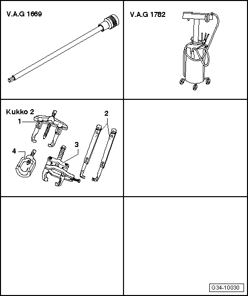
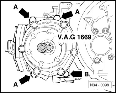
| t | Hexagon key -V.A.G 1669- |
| t | Used oil collection and extraction unit -V.A.G 1782- |
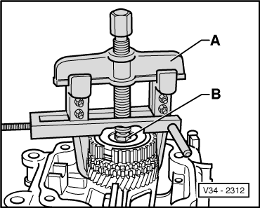
| t | -1-Two-arm puller -Kukko 20/10- with hook -Matra V170- |
| t | Stud M8x100 mm |
|
|
 Note
Note
|
|
|
|
Note
|
|
|
|
|
|
Note
|
|
|
|
|
|
|
|
|
|
|
|
Note
|
|
Note
|
|
|
|
Note
|
|
|
|
Note
|
|
|
|
|
|
|
|
|
|
|
|
|
|
|
|
|
|
|
|
|
|
Note
|
|
|
|
|
|
Note |
|
Note
|
|
|
|