audi Workshop Repair Guides

Audi Workshop Service and Repair Manuals

Adjusting engine mounting > < Attaching engine to repair stand
4-cylinder Engine (2-valve), Mechanical Components
Removing and installing engine
Installing

Special tools and workshop equipment required

  • ◆ Depth gauge (for vehicles with automatic gearbox)

Procedure

  • ● Engine installed on engine bracket T10012.

Installation is carried out in the reverse order to removal, noting the following:

Notes:

  • ◆ When installing the engine all cable ties must be fitted in the same position.
  • ◆ Secure all hose connections with the correct hose clamps (same as original equipment):

=> Parts List

  • ◆ When performing installation procedures always replace self-locking nuts and bolts.
  • ◆ Replace seals, gaskets, and bolts which have a specified tightening angle.
  • ‒ Check whether the dowel sleeves for centralising engine/gearbox are in the cylinder block, install if necessary.
 
A10-0129
  • ‒ → Engage intermediate plate on sealing flange and push onto dowel sleeves -arrows-.

Vehicles with manual gearbox:

  • ‒ If necessary, check that clutch plate is properly centred.
  • ‒ Check clutch release bearing for wear, replace if necessary.
  • ‒ Lightly lubricate clutch release bearing, release bearing guide sleeve and splines on input shaft with G 000 100.
  • ‒ Attach gearbox to engine.

Notes:

  • ◆ The tightening torques listed on this page apply only to lightly greased, oiled, phosphated, or black finished nuts and bolts.
  • ◆ Additional lubricant such as engine or gearbox oil may be used, but do not use graphite lubricant.
  • ◆ Do not use degreased parts.
  • ◆ Tightening torque tolerance ±15%.
 
A37-0214

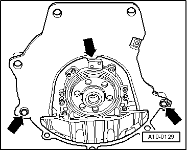
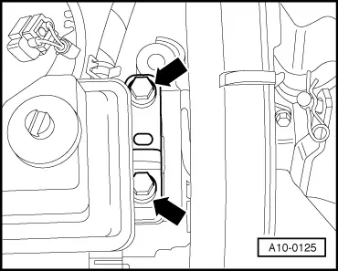
→ Engine/gearbox mountings (manual gearbox)

Item

Bolt

Nm

1, 2 1)

M12 x 65

80

3 1), 4 1)

M12 x 180

80

5...7

M10 x 50

45

8

M12 x 80

80

    1)    Bolt with threaded pin M8

A: Centring sleeves

 
A34-0234
  • ‒ → Push in splash plate -2- in such a way that the lower lug engages into the cylinder block and secure on top with bolt -1-.
 
A32-0007

Vehicles with automatic gearbox:

  • ‒ To secure the torque converter on the drive plate only use the correct nuts as specified in the parts catalogue.

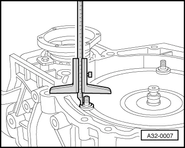
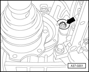
=> Parts List

→ If the torque converter is correctly installed, the depth between the contact surfaces at the bottom of the studs on the torque converter and the contact surface of the torque converter bell housing is about 22 mm.

If the torque converter has not been completely inserted, this distance will be approx. 10 mm.

Important
If the torque converter is not installed correctly, the torque converter drive plate or the ATF pump will be seriously damaged when the gearbox is joined to the engine.
 
A37-0201
  • ‒ → Before installing engine, rotate torque converter and drive plate so that one hole/one stud are level with the aperture of the torque converter cover plate -arrow-.
  • ‒ Attach gearbox to engine.
  • ‒ Secure nuts of torque converter with special tool Matra V/175.

Notes:

  • ◆ The tightening torques listed on this page apply only to lightly greased, oiled, phosphated, or black finished nuts and bolts.
  • ◆ Additional lubricant such as engine or gearbox oil may be used, but do not use graphite lubricant.
  • ◆ Do not use degreased parts.
  • ◆ Tightening torque tolerance ±15%.
 
A37-0214

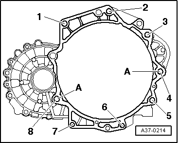
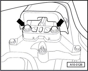
→ Fastening engine to gearbox in vehicles with automatic gearbox

Item

Bolt

Nm

1, 2 1)

M12 x 65

80

3 1), 4 1)

M12 x 180

80

5...7

M10 x 50

45

8

M12 x 80

80

    1)    Bolt with threaded pin M8

A: Centring sleeves

 
A10-0125

All models:

  • ‒ Guide engine/gearbox assembly into the chassis.
  • ‒ → Unscrew bolts -arrows- engine mounting from engine console...

 
A10-0126
  • ‒ → ...and gearbox mounting on gearbox console hand tight.
  • ‒ Only use new bolts to secure.

Note:

The bolts are tightened to final torque only after adjusting the engine mounting .

  • ‒ Remove engine mounting T10012 from engine.
  • ‒ Install drive shafts.

=> Running Gear, FWD and 4WD; Repair group 40

Note:

Before further assembly carry out the installation of the drive shafts.

  • ‒ Install the connecting rod.

=> Running Gear, FWD and 4WD; Repair group 40

 
N34-0712
  • ‒ → First attach pendulum support to gearbox -arrows B- and then to subframe -arrows A-.
  • ‒ Only use new bolts to secure.
  • ‒ Install exhaust system and align it stress-free => Page 26-19.
  • ‒ Drive bushes for the securing bolts back slightly to facilitate positioning of the vane pump and air conditioner compressor.
  • ‒ Install the vane pump and the air conditioner compressor => Page 13-4.

Vehicles with manual gearbox:

  • ‒ Install hydraulic clutch slave cylinder:

=> 5-speed Manual Gearbox 02K; Repair group 30; Servicing clutch release mechanism

  • ‒ Attach shift mechanism to gearbox and adjust:

=> 5-speed Manual Gearbox 02K; Repair group 34; Servicing shift mechanism

All models:

  • ‒ Install ribbed belt=> Page 13-11.
  • ‒ Adjust engine mounting => Page 10-66.

Vehicles with throttle cable:

  • ‒ Adjust throttle cable:

=> Fuel Supply System - Petrol Engines; Repair group 20; Servicing throttle mechanism - Vehicles with mechanical throttle mechanism

All models:

  • ‒ Electrical connections and routing:

=> Current Flow Diagrams, Electrical Fault-finding and Fitting Locations

Notes:

  • ◆ If the battery is reconnected, please ensure that the vehicle equipment (radio, radio/navigation system, clock, electric window lifters) is activated as described in the operating instructions.
  • ◆ Deactivate the service mode of the telematics control unit.

=> Radio, Telephone and Navigation System; Repair group 91

  • ◆ Further measures after reconnection of voltage supply:

=> Simos Fuel Injection and Ignition System; Repair group 24

  • ‒ Check oil level => Page 17-22.
  • ‒ Top up coolant => Page 19-52.

Notes:

  • ◆ Drained coolant may only be used again if the original cylinder head and cylinder block are re installed.
  • ◆ Coolant must not be used again if it is dirty.
Important
Do not use charging unit for boost starting. There is danger of damaging the vehicle control units.

Tightening torques

Component

Nm

Bolts/nuts

M6

10

M8

20

M10

45

M12

65

Except for the following:

Drive plate to torque converter

M10 x1

85

Pendulum support to gearbox

40 + 90° 1)2)

Pendulum support to subframe

20 + 90°1)2)

Air conditioner compressor to bracket for auxiliary mechanical units

45

Battery cable clamp to battery terminal

6

    1)    90°corresponds to a quarter of a turn

    2)    Replace nuts and bolts

Adjusting engine mounting > < Attaching engine to repair stand