
A3 Mk1
|
Checking ignition system
Checking coolant temperature sender -G62
|
 |
|
|
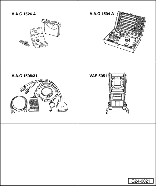
Special tools and workshop equipment required
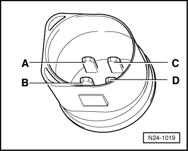
Fitting location => Fitting locations overview, Page 24-5 Test requirements:
Test sequence
|
 |
|
|
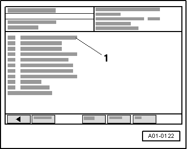
→ Display on VAS 5051:
|
 |
|
|
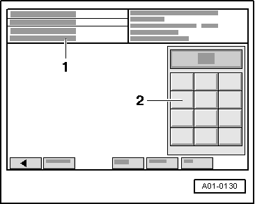
→ Display on VAS 5051:
|
 |
||||||||||||||||||||||||||||||||||||
|
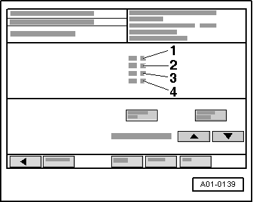
→ Display on VAS 5051:
If display zone 3 shows an implausible value:
| ||||||||||||||||||||||||||||||||||||
 |
|
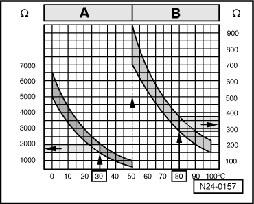
Range A shows resistance values for temperature range 0...50 °C and range B shows the values for temperature range 50...100 °C. |
 |
|
|
→ Sample readings:
If specified value is not attained:
If specified value is attained:
|
 |
|||||||
If no wiring fault is detected:
|