
A3 Mk1
|
Checking ignition system
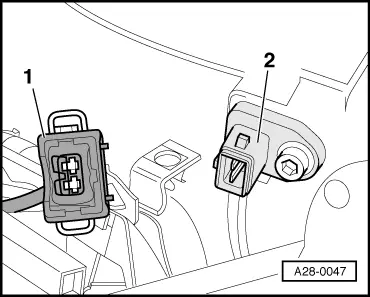
Checking intake air temperature sender -G42
|
 |
|
|
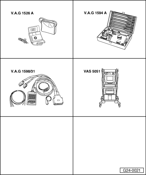
Special tools and workshop equipment required
Fitting location => Fitting locations overview, Page 24-5 Test sequence
|
 |
|
|
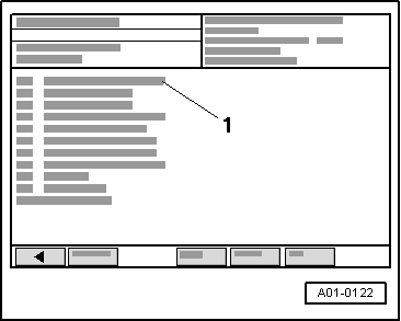
→ Display on VAS 5051:
|
 |
|
|
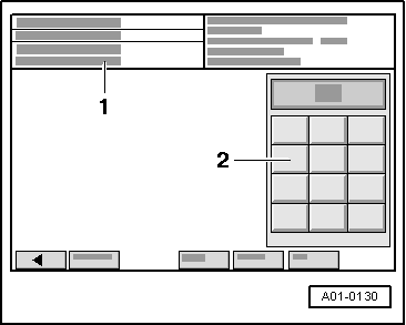
→ Display on VAS 5051:
|
 |
|
|
 |
|||||||
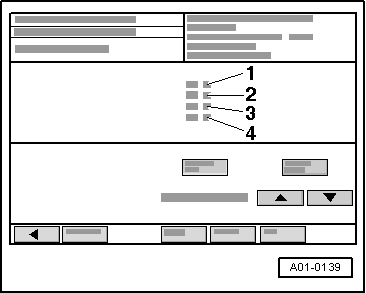
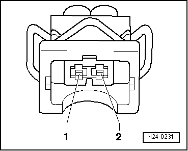
If no wiring fault is detected:
Checking sender: |
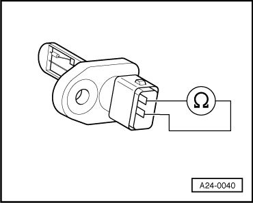 |
|||||||||||||
Specifications:
If specified value is not attained:
|