audi Workshop Repair Guides

Audi Workshop Service and Repair Manuals

Removing and installing spring > < Removing and installing anti-roll bar
Running gear, Front-wheel drive and four-wheel drive
Servicing rear axle - Four-wheel drive vehicles
Exploded view of spring and shock absorber
 
N42-0373
  • Bolt, 60 Nm
    • ◆ Always replace after removing
  • Mounting bracket for shock absorber
  • Shock absorber
    • ◆ Only to be replaced in pairs up to vehicle ident no. 8L_YA_117 500
    • ◆ Assignment to vehicle => Vehicle data sticker, Page 00-2
    • ◆ Checking shock absorber for leaks
    • ◆ Checking shock absorber following removal => Page 00-11
    • ◆ Before scrapping defective shock absorbers, always ensure gas release and draining => Page 00-7
 
N42-0373
  • Anti-roll bar
    • ◆ Removing and installing
  • Nut, 25 Nm
    • ◆ Self-locking
    • ◆ Always replace after removing
  • Bolt, 110 Nm
    • ◆ Always replace after removing
  • Connecting link
  • Trailing arm
    • ◆ Different versions => Fig.1
  • Spacer
    • ◆ For vehicles with heavy-duty running gear only; distinguishing feature
      => vehicle data sticker, Page 00-2
 
N42-0373
  • Buffer stop
    • ◆ Different versions => Fig.1
    • ◆ Tighten version with threaded pin to 10 Nm
  • Coil spring
    • ◆ Assignment to vehicle => Vehicle data sticker, Page 00-2
    • ◆ Check for paint damage and eliminate any damage
    • ◆ Heed colour coding
    • ◆ Installation position: Coloured mark on spring points downwards towards buffer stop
    • ◆ Removing and installing
  • Spring seat
 
N42-0373
  • Thread in longitudinal member
    • ◆ Thread in body can be repaired using threaded wire insert as per DIN 8140 (Heli-Coil)
      Threaded insert must be of same length as thread in body
Attention:
Repair work using Heli Coil may only be performed at two nuts per side.
  • Thread in cross member
    • ◆ Thread in body can be repaired using threaded wire insert as per DIN 8140 (Heli-Coil)
      Threaded insert must be of same length as thread in body
 
A42-0324

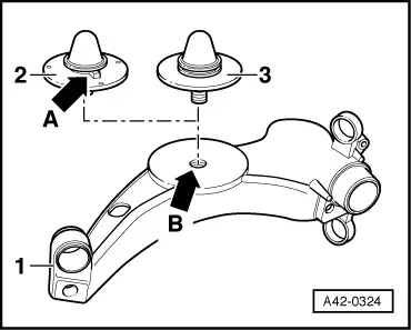
→ Fig.1    Different trailing arms and buffer stops

A modified trailing arm -1- and a modified buffer stop -2- have been fitted as of approx. 06.99.

  • ‒ Installation of a new buffer stop -2- with locating pin in a trailing arm prior to 06.99 involves enlarging thread -arrow B- in trailing arm to ø 10.5 mm. Locating pin on underside also has to be cut off.
  • ‒ Heed the following on installation: Start of spring winding must make contact with web -arrow A-.

Note:

Buffer stop -3- with threaded pin (version up to approx. 06.99) is tightened to 10 Nm.

Removing and installing spring > < Removing and installing anti-roll bar