
A3 Mk1
|
Servicing rear axle - Front-wheel drive vehicles
Removing and installing hydraulic bonded rubber bush
|
 |
|
|
 |
|
|
 |
|
Vehicles with dynamic headlight range control
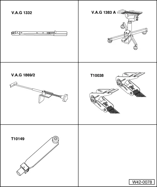
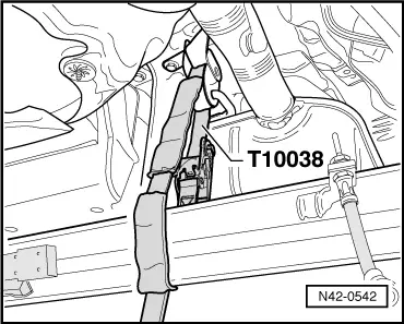
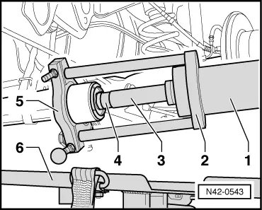
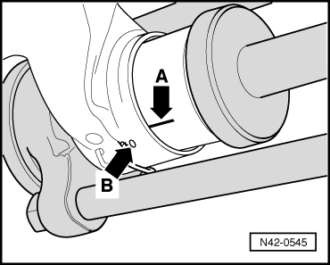
Continued for all vehicles Note: Place engine/gearbox jack V.A.G 1383 A with universal gearbox support V.A.G 1359/2 under suspension link (to prevent risk of accidents caused by parts dropping when bush is pulled out). Pressing out core of hydraulic bonded rubber bush |
 |
|
Notes:
|
 |
|
|
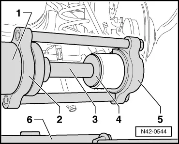
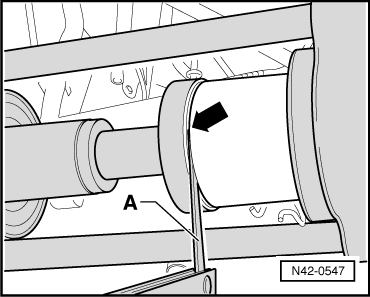
Pressing out sleeve of hydraulic bonded rubber bush
Note: The marking "Top" on VAS 6180/2 must face towards suspension link. |
 |
|
|
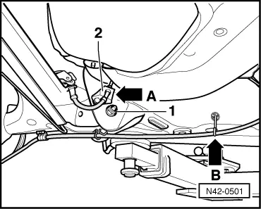
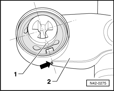
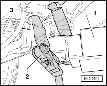
Installing Use only "conventional" bonded rubber bushes when installing → End face of bonded rubber bush has markings -1-. These markings must line up with the edge -arrow- on the trailing arm -2-.
|
 |
|
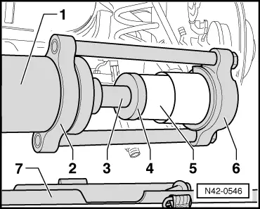
Note: The marking "Top" on VAS 6180/2 must face towards suspension link. |
 |
|
|
 |
|
Securing vehicle to lifting platform There is a risk of the vehicle slipping off the lifting platform if it is not secured properly. |
 |
|
|
 |
|||||
|
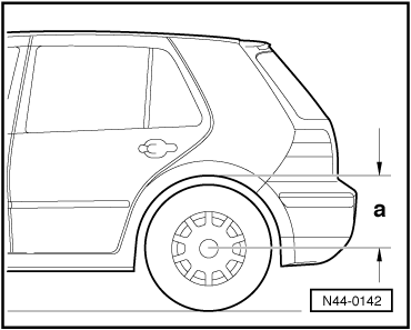
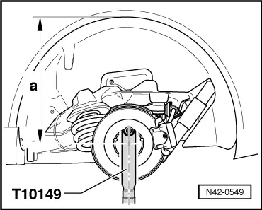
→ Only tighten the bolts securing the rear axle to the mounting bracket when the distance -a- between the centre of the wheel hub and the lower edge of the wheel housing is the same as the distance measured before starting work. Otherwise the bonded rubber bush will be under load, and service life will be reduced.
Caution
Perform remaining installation steps in reverse sequence of removal.
=> Brake system; Repair group 47; Bleeding brake system
|