| In-vehicle Repair Special Tool(s) | | Installer, oil seal 303-039 (21-009B) | | | Lifting equipment, engine 303-122 (21-068A) | | | Adjusting tool, camshaft TDC setting 303-376 (21-162B) | | | Socket wrench, cylinder head bolts 303-392 (21-167) | General Equipment Spatula Wooden block Trolley jack Workshop hoist Engine lifting eye (part no. 938F 17A084 AF) Materials Name Specification Sealant, camshaft bearing caps WSK-M4G348-A5 Seal remover WSK-M2G348-A4 Engine oil WSS-M2C912-A1 Silicone grease for spark plug connector seal A969-M1C171-A4 Never Seeze Removal | | -
General - Make a note of the radio keycode.
- Make a note of the preset radio stations.
- Owing to special model variants, some job steps do not apply to all vehicles. These are clearly marked in the text.
- Cable ties : cut if necessary and renew them on installation.
| | | -
WARNING:To prevent the risk of scalding, place a thick cloth over the filler cap before opening the cooling circuit. Failure to do so can result in injury. Open the coolant expansion tank. | | | -
Detach the pulley cover (if present). | | | -
WARNING:Danger of scalding if the engine is hot. Drain the coolant at the coolant hose. - After draining, reattach the coolant hose.
| | | -
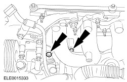
Unscrew the nuts and studs from the power steering pump bracket (shown from above with the heat shield removed). | | | -
Disconnect the plug for the crankshaft position sensor (CKP sensor). | | | -
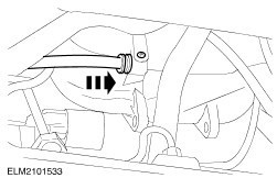
Detach the brake servo pipe from the inlet manifold. - Release the quick release coupling and pull out the pipe.
| | | -
Pull off the oil pressure switch plug and the knock sensor plug (KS) (if present). | | | -
Remove the intake pipe with air cleaner housing. - Disconnect the mass air flow (MAF) sensor plug (if present).
- Disconnect the intake air temperature (IAT) sensor multiplug (if present).
- Remove one bolt and two nuts.
| | | -
Remove the intake pipe with air cleaner housing. - Detach the positive crankcase ventilation (PCV) hose.
- Detach the intake hose.
- Remove the air cleaner housing from the rubber bushes.
| | | -
NOTE:This step only applies to vehicles with liquid propane gas (LPG) drive. | | | -
NOTE:This step only applies to vehicles with liquid propane gas (LPG) drive. Detach the bracket for the power steering line from the cylinder head. | | | -
NOTE:This step only applies to vehicles with liquid propane gas (LPG) drive. Install the engine lifting eye in place of the bracket for the power steering line. | | | -
Detach the cruise control system cable (if present). - Detach the cable from the throttle plate.
- Pull the cable out of the bush while gently moving it up and down.
- Press the bush out of the bracket.
| | | -
Detach the accelerator cable. - Pull off the plastic clip and lay the accelerator cable to one side.
| | | -
WARNING:When performing operations on or in the vicinity of fuel system components, do not smoke or work with naked flames. Highly flammable vapours are always present, which may be ignited. Failure to observe these instructions can lead to personal injury. | | | -
Pull off the vacuum hoses and disconnect the plug. | | | -
Detach the wiring rail from the inlet manifold. - Disconnect the positive cable at the fuse element and unclip the fuse element from the wiring rail (if present).
- Remove the three bolts.
- Cut the cable tie.
| | | -
Disconnect the EGR hoses (if present). | | | -
Detach the coolant hoses from the thermostat housing. | | | -
Disconnect the plugs. - From the radio interference suppressor.
- From the ignition coil (EI).
| | | -
Disconnect the connector from the coolant temperature gauge sender. | | | -
Detach the heat shield. - Remove the upper bolts.
- Remove the coolant hose bracket.
- Detach the air conditioning line bracket.
- Remove the lower bolts.
| | | -
Detach the exhaust pipe from the exhaust manifold. | | | -
Detach the oil dipstick tube and the power steering fluid line bracket. | | | -
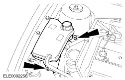
Detach the power steering fluid reservoir (1 bolt). | | | -
Detach the coolant expansion tank. - Unclip the cruise control system cable from the coolant expansion tank.
- Lay the coolant expansion tank to one side.
| | | -
Detach the bracket from the power steering pump. - Lay the bracket and pump to one side.
| | | -
Remove the generator. - Release the bolt.
- Remove the bolt.
| | | -
Unscrew the upper bolt from the generator bracket. | | | -
Measure the valve clearance, if necessary. | | | -
Unscrew the bolts of the camshaft bearing caps evenly in several stages, two turns at a time. - Remove the tappets and keep them in order.
| | | -
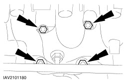
CAUTION:Mark the bolts to be reused with one or two punch marks. Bolts can be reused twice. Discard bolts as necessary. CAUTION:The cylinder head must be cooled to ambient temperature. Remove the cylinder head bolts. | | | -
Lift off the cylinder head. - Hook the special tool into the engine lifting eyes.
- Lift off the cylinder head using a workshop hoist and place it on clean wooden blocks.
| Installation | | -
Preparatory operations. - Thoroughly clean the threaded holes of the cylinder head bolts.
| | | -
Make up two locating studs as shown in the diagram. | | | -
CAUTION:The selection of cylinder head gasket depends on the cast cylinder block number. Lay a new cylinder head gasket on the cylinder block and position the cylinder head. - Cylinder block number.
- Fit a new cylinder head gasket.
- Insert the fabricated locating studs.
- Check that the guide sleeves are correctly seated.
- Position the cylinder head on the cylinder block.
| | | -
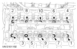
CAUTION:The cylinder head bolts must not be retightened. Tighten the cylinder head using the special tool in three stages, in the sequence indicated. - Stage 1: Tighten the bolts to 15 Nm.
- Stage 2: Tighten the bolts to 40 Nm.
- Stage 3: Tighten the bolts by 90 degrees.
- Coat the tappets with engine oil and install them in the positions from which they were removed.
| | | -
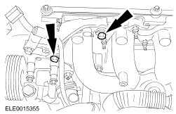
Apply sealant to camshaft bearing caps nos. 0 and 5, in the areas shown. | | | -
Turn the crankshaft to approx. 60 degrees BTDC. | | | -
NOTE:Identification numbers are provided on the outer face of the camshaft bearing caps. Insert the camshafts so that none of the cams is at full lift. - Lubricate the camshaft and camshaft bearing caps with engine oil .
| | | -
NOTE:Screw in the camshaft bearing cap bolts evenly, in the sequence shown, a half turn at a time and tighten them in two stages. Tighten the bolts of the camshaft bearing caps. | | | -
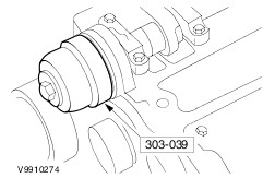
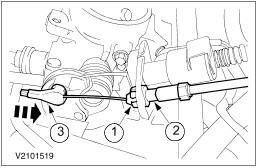
Fit the camshaft oil seals. - Lubricate the camshafts and the sealing lip of the oil seals with engine oil .
- Draw in the new oil seals using the special tool, washer and M10 x 70 bolt.
| | | -
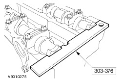
Turn the camshafts to ignition position for cylinder no. 1 and insert the special tool into the camshafts. | | | -
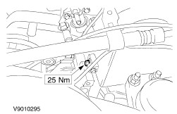
Attach the power steering pump bracket. - Move the bracket with the power steering pump into the installation position.
- Screw in the upper bolts and tighten them.
| | | -
Connect the vacuum hoses to the EGR valve (if present). | | | -
Attach the oil dipstick tube and the power steering fluid line bracket. | | | -
Attach the exhaust pipe with a new gasket to the exhaust manifold. | | | -
Fit the upper bolt to the generator bracket. | | | -
Fit the studs and nuts of the bracket for the power steering pump (shown from above with the heat shield removed). | | | -
Connect the oil pressure switch plug and the KS, if present. | | | -
Attach the brake booster pipe to the intake manifold. | | | -
Attach the heat shield. - Insert the oil dipstick tube, position the coolant hose bracket and engine lifting eye.
- Insert the upper bolts.
- Attach the bracket to the air conditioning line.
- Insert the lower bolts.
| | | -
Attach the power steering fluid reservoir. | | | -
Attach the belt pulley cover (if removed). | | | -
Attach the connector for the coolant temperature gauge sender. | | | -
Attach the coolant hoses to the thermostat housing. | | | -
Connect the plugs. - To radio interference suppressor.
- To the ignition coil (EI)
| | | -
CAUTION:Do not bend the fuse element when tightening the nut, as this could cause it to break. Attach the wiring rail to the intake manifold. - Clip the fuse element to the wiring rail and connect the positive cable to the fuse element (if present).
- Insert the three screws.
- Connect the cable tie.
| | | -
Connect the vacuum hoses to the inlet manifold and connect the plug. | | | -
WARNING:When performing operations on or in the vicinity of fuel system components, do not smoke or work with naked flames. Highly flammable vapours are always present, which may be ignited. Failure to observe these instructions can lead to personal injury. Connect the fuel pipes. | | | -
Attach and adjust the accelerator cable. - Insert the cable into the bracket and push on the plastic clip.
- Detach the clip from the accelerator cable.
- Pull the inner cable a few clicks out from the outer cable.
- Fully depress the accelerator pedal once and push the clip back on.
- Check that the throttle plate opens fully when the accelerator pedal is depressed. If not, repeat the adjustment procedure.
| | | -
Attach the cruise control system cable. - Press the bush into the bracket.
NOTE:It is engaged properly when heard to click. - Push the cable into the bush.
- Attach the cable to the throttle plate.
| | | -
NOTE:This step only applies to vehicles with liquid propane gas (LPG) drive. Remove the engine lifting eye. | | | -
NOTE:This step only applies to vehicles with liquid propane gas (LPG) drive. Attach the bracket for the power steering line. | | | -
NOTE:This step only applies to vehicles with liquid propane gas (LPG) drive. | | | -
Install the intake pipe with air cleaner housing. - Press the air cleaner into the rubber bushes.
- Attach the positive crankcase ventilation hose.
- Attach the intake hose.
| | | -
Install the intake pipe. - Connect the MAF sensor plug.
- Connect the IAT sensor plug.
- Insert one bolt and fit two nuts.
| | | -
Standard finishing operations: - Connect the battery ground cable.
- Close the coolant expansion tank.
- Check the fluid levels and correct as necessary.
- Check the routing of vacuum hoses and the wiring and secure them with cable ties .
- Reprogram the preset radio stations.
- Carry out a road test to enable the PCM to collect data.
- Check the fluid levels again and correct as necessary.
| | |