| Removal Special Tool(s) | | Remover, front axle driveshaft 308-192 (16057) | | | Adjusting tool, gearshift mechanism neutral position 308-273 (16088) | | | Remover, fuel pipe 3/8" (yellow) 310-D004 (23039) | | | Remover, fuel pipe 1/2" (green) 310-D005 (23040) | | | Lifting equipment, engine 303-122 (21068A) | General Equipment Assembly plugs Assembly table Retaining strap Workshop hoist Materials Name Specification Cable ties Removal All vehicles | | -
General - Make a note of the radio keycode.
- Make a note of the pre-programmed radio stations.
- The position markings for the engine mountings and engine roll restrictors are described looking from the transmission towards the engine.
- Due to special model variants, some job steps do not apply to all vehicles. These are clearly marked in the text.
- Cable ties : cut if necessary and renew them on installation.
| | | -
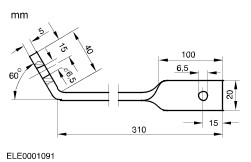
Fabricate an auxiliary tool to fix the hood in open position. | | | -
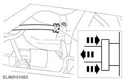
Lock the gearshift lever inside the vehicle using the special tool. - Shift the gearshift mechanism to "neutral".
- Unclip and pull up the boot and bellows.
| | | -
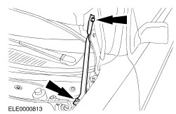
Open the hood and attach the auxiliary tool to the hood. | | | -
NOTE:Prevent the assembly from turning Slacken the suspension strut retaining nuts on the right and left sides by five turns. | | | -
WARNING:To prevent the risk of scalding, place a thick cloth over the filler cap before opening the cooling circuit. Release the coolant circuit pressure. - Carefully open the filler cap.
| | | -
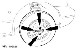
Loosen the wheel nuts for both front wheels. | | | -
Remove both front wheels. | | | -
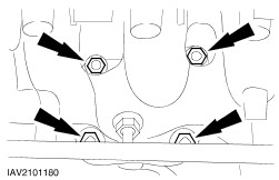
Detach the lower radiator cover (nine bolts) and the bumper braces (left side shown). | | | -
WARNING:Danger of scalding if the engine is hot. Drain the coolant. - Retighten the drain plug.
| | | -
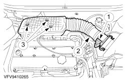
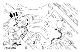
Remove the intake pipe with air cleaner housing. - Disconnect the mass air flow (MAF) sensor plug.
- Disconnect the intake air temperature (IAT) sensor multiplug.
- Remove one bolt and two nuts.
| | | -
Remove the intake pipe with air cleaner housing (continued). - Detach the positive crankcase ventilation (PCV) hose.
- Detach the intake hose.
- Remove the air cleaner housing from the rubber bushes.
| | | -
Detach the cable and disconnect the plug. - Battery positive cable
- Disconnect the plug.
- Ground cable
| | | -
Detach the central junction box (CJB) and lay it to one side. | | | -
Remove the battery tray (continued). | | | -
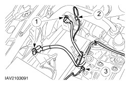
Detach the main harness from the Powertrain Control Module (PCM). - Remove the power steering fluid reservoir (plugged in) and lay it to one side.
- Open the cable fastener.
- Detach the ground leads (2 off).
- Detach the main harness connector from the PCM.
| | | -
Detach the ground lead from the engine lifting eye and pull out the power steering pressure connector. | | | -
Detach the leads. - Engine wiring harness connector
- Automatic transmission ground lead
- Cable tie
| | | -
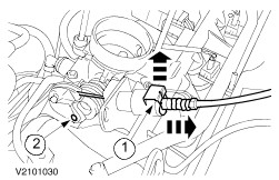
Detach the speed control cable (if present). - Detach the cable from the throttle plate.
- Carefully move the cable up and down and pull it out of the clip.
- Remove the clip.
| | | -
Detach the accelerator cable. - Pull out the clip.
- Unhook the accelerator cable.
| | | -
Detach the vacuum hoses from the inlet manifold. | | | -
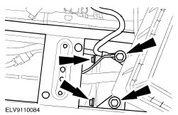
Remove the heat shield. - Remove the upper bolts.
- Remove the brackets for the coolant hoses and remove the oil dipstick.
- Remove the lower bolt.
- Remove the coolant pipe bracket.
| | | -
Remove the coolant pipe. - Remove the coolant pipe.
- Detach the coolant hose from the coolant pipe.
- Detach the coolant hose from the coolant pump.
| | | -
Detach the catalytic converter from the exhaust manifold. | Vehicles with air conditioning | | -
Disconnect the plug for the A/C compressor (shown with drive belt removed). | All vehicles | | -
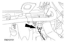
Disconnect the engine coolant temperature sensor (ECT sensor) plug. | | | -
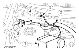
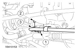
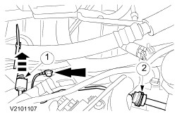
Disconnect the plug and detach the upper coolant hoses. - Unclip the cable.
- Detach the coolant hoses.
- Disconnect the fan motor plug.
| | | -
Detach the wiring clamp from the fender apron panel and the coolant hoses. | | | -
Remove the upper drive belt cover. | | | -
WARNING:Brake fluid will escape. Observe the safety regulations for working with brake fluid. CAUTION:Close off the openings. Disconnect the clutch slave cylinder. - Pull out the clip and detach the pipe.
- Detach the slave cylinder pipe from the transmission and tie it up.
- Disconnect the ground lead from the transmission.
| | | -
Remove the lower wheel housing trim panels (right side shown). | | | -
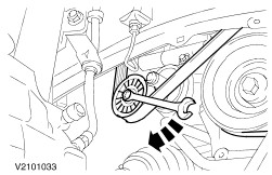
Slacken and remove the drive belt. | | | -
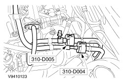
Detach the brake booster vacuum pipe from the intake manifold. - Release the quick-release coupling and pull out the pipe.
| | | -
Disconnect the heated oxygen sensor (HO2S) plug. | | | -
Disconnect and unhook the front exhaust pipe. | | | -
CAUTION:Do not damage the boots and the ABS sensor ring. Detach the lower suspension arm ball joint on both sides. - Detach the ABS sensor cable bracket from the suspension strut.
| | | -
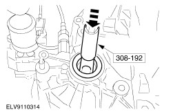
CAUTION:The inner joint must not be bent by more than 18°; the outer joint must not be bent by more than 45°. Detach the right front axle driveshaft centre bearing. - Pull the right front axle driveshaft out of the transmission and tie up with the intermediate shaft.
| | | -
CAUTION:The inner joint must not be bent by more than 18°; the outer joint must not be bent by more than 45°. Detach the left front axle driveshaft from the transmission and tie it up. | | | -
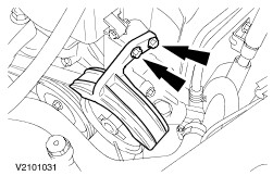
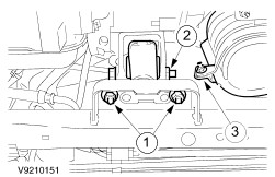
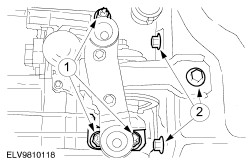
Remove the right engine roll restrictor. - Unscrew the centre bolt.
- Remove the bolts.
| | | -
Detach the bracket for the right engine roll restrictor from the transmission. | | | -
NOTE:If necessary, raise the transmission slightly. Remove the left engine roll restrictor and the catalytic converter. - Unscrew the nuts.
- Unscrew the centre bolt.
- Loosen the catalytic converter bracket.
- Remove the catalytic converter.
| Vehicles with air conditioning | | -
Detach the air-conditioning system dehydrator and tie it up. | All vehicles | | -
Detach the lower coolant hoses. | Vehicles with air conditioning | | -
Detach the air conditioning compressor and tie it up. | All vehicles | | -
Detach the shift cables from the transmission. - Detach the shift cable from the gearshift lever.
- Tension the abutment bracket by twisting it anti-clockwise, and remove the cable from the bracket.
- Detach the shift cable from the gearshift lever.
- Tension the abutment bracket by twisting it anti-clockwise, and remove the cable from the bracket.
- Release the adjustment mechanism by pressing it in.
| | | -
Detach the coolant expansion tank and lay it to one side. - Detach the speed control cable (if present) from the coolant expansion tank.
| | | -
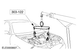
Attach the special tool and raise the engine slightly using a workshop hoist . | | | -
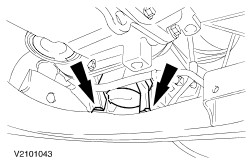
NOTE:Mark the installation position. Remove the front engine mounting. - Unscrew the nuts.
- Slacken the bolts by two turns.
| | | -
NOTE:Mark the installation position. Remove the rear engine mounting. - Unscrew the nuts.
- Remove the bolts.
| | | -
CAUTION:Do not subject the hoses and pipes to tension. NOTE:Raise the engine and transmission assembly until the power steering pump is accessible. Detach the power steering pump and tie it up using cable ties . | | | -
CAUTION:Do not subject to tension or damage the air conditioning system pipes or hoses. Remove the engine and transmission assembly. | | | -
Disconnect the plug for the reversing lamp switch and the vehicle speed sensor (VSS). | | | -
Disconnect the starter motor. | | | -
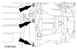
Unscrew the upper flange bolts. - Upper starter motor bolts.
- Disconnect the ground lead from the transmission.
| | | -
Remove the flange bolts on the right side of the transmission and the lower starter motor bolt. - Remove the starter motor with the wiring harness.
| | | -
Remove the flange bolts on the left side of the transmission. | | | -
Separate the transmission from the engine. | |