| Disassembly Special Tool(s) | | Slide Hammer 205-047 (15011) | | | Universal flange holding wrench 205-072 (15030A) | | | Locking tool, flywheel 303-254 (21135) | | | Mounting bracket 303-435-04 (21064) | | | Mounting Plate 303-435-12 (21-150A) | | | Pliers, spark plug connector 303-622 (21-226) | | | Remover, oil pan 303-633 (21-227) | General Equipment Wooden blocks Retaining straps Workshop hoist Disassembly All Vehicles | | -
General - The engine remains hooked into the jib crane until the assembly stand can be attached.
- If the engine is on the assembly stand and needs to be unhooked temporarily from the jib crane, secure the engine using a retaining strap .
| | | -
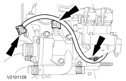
Remove the camshaft position (CMP) sensor plug and the engine coolant temperature (ECT) sensor plug. - Unclip the cable from the ignition coil (EI).
| | | -
Remove the oil pressure switch plug and the knock sensor (KS). | | | -
Remove the generator. - Pull out the plugs.
- Detach the positive lead.
- Undo the bolt.
- Release the bolt.
| | | -
Detach the intake manifold. - Disconnect the solenoid valve plug
- Unscrew and remove seven bolts and two nuts.
| | | -
Detach the parts mounted on the inlet side. - Generator Mounting Bracket
- Oil filter
- Knock sensor (KS)
- Oil pressure switch
| | | -
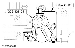
Attach the engine to the assembly stand. - Fit the mounting plate.
- Fit the mounting bracket.
- Attach the engine to the assembly stand.
| | | -
Detach the parts mounted on the outlet side. - Coolant hose from coolant pump and thermostat housing
- Bracket from power steering pump
- Bracket from A/C compressor
| | | -
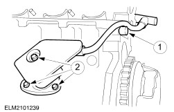
Detach the positive crankcase ventilation. - Positive crankcase ventilation pipe
- Undo the three bolts.
| | | -
Detach the timing belt cover. - Detach the coolant pump belt pulley.
- Remove the drive belt idler pulley.
- Detach the timing belt center cover/front engine mounting bracket.
- Remove the upper timing belt cover.
NOTE:Immobilize the flywheel with Special Tool 303-254. - Detach the crankshaft belt pulley.
- Remove the lower timing belt cover.
| | | -
CAUTION:Do not pull the cable when removing the spark plug connector. If necessary, remove the ignition cables from the ignition coil to avoid kinking the cables. Turn the spark plug connector slightly before removing to loosen the seal. CAUTION:Pull off the spark plug connectors in line with the spark plugs (for bent spark plug connectors use Special Tool 303-622). CAUTION:The spark plugs must be removed to adjust the valve timing. NOTE:Loosening sequence: from the outside to the inside, working diagonally. Remove the spark plugs and the cylinder head cover. - Disconnect the HT leads from the spark plugs.
- Unscrew the bolts.
- Remove the spark plugs.
| Vehicles built up to 1/1999 inclusive | | -
NOTE:Designs with lower idler pulley shown (built until about 01/99). NOTE:Position of the crankshaft pulley and thrust washer. Detach the timing belt drive and the coolant pump. - Loosen the bolt, slacken the timing belt tensioner by turning clockwise and remove it.
- Remove the timing belt.
- Detach the upper idler pulley.
- Detach the lower idler pulley.
- Remove the coolant pump.
- Detach the crankshaft timing pulley and the thrust washer.
| Vehicles built from 1/1999 | | -
NOTE:Designs without lower idler pulley shown (built from about 01/99). NOTE:Position of the crankshaft pulley and thrust washer. Detach the timing belt drive and the coolant pump. - Loosen the bolt, slacken the timing belt tensioner by turning clockwise and remove it.
- Remove the timing belt.
- Detach the idler pulley.
- Remove the coolant pump.
- Detach the crankshaft timing pulley and the thrust washer.
| | | -
Remove the camshaft timing pulleys. | | | -
NOTE:Unscrew the bolts evenly in several stages two turns at a time, according to the bolt-slackening sequence. Detach the camshaft bearing cap. - Remove the tappets and keep them in order.
| | | -
CAUTION:Mark the bolts to be reused with one or two punch marks. Bolts can be reused twice. Discard bolts as necessary. CAUTION:The cylinder head must be cooled to ambient temperature. NOTE:Slackening sequence. Undo the cylinder head bolts. | | | -
Lift off the cylinder head. - Hook the jib crane into the engine lifting eyes, raise the cylinder head and place it onto clean wooden blocks .
| | | -
Detach the clutch pressure plate and the clutch disc. | | | -
Detach the flywheel/drive plate. | | | -
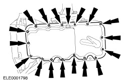
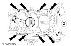
Remove the drain plug and the oil pan bolts. | | | -
CAUTION:Avoid damaging the mating faces by using only the special tool listed to detach the oil sump. Do not use a chisel or screwdriver to detach the oil sump. Detach the oil pan. - Attach the special tools and lock against the oil sump. Detach the oil sump from the lower crankcase by tapping several times.
| | | -
Detach the oil intake pipe and the lower crankcase. - Oil intake pipe bolts.
- Detach the lower crankcase bolts.
| | | -
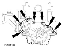
Detach the rear crankshaft oil seal housing and the crankshaft position (CKP) sensor with the bracket. - Bolt from CKP sensor
- Four oil seal housing bolts
| | | -
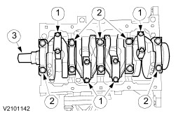
NOTE:Keep all parts in order. Remove the crankshaft and the pistons. - Remove the big-end bearing caps.
- Remove the main bearing caps.
- Remove the crankshaft and push out the pistons with connecting rods.
| |