| Removal Special Tool(s) | | Support Bar, Engine 303-290 (21140) | | | Adaptor for 303-290 303-290-01 (2114001) | | | Adaptor for 303-290 303-290-02 (2114002) | | | Adaptor for 303-290 303-290-03 (2114003) | | | Wrench, Intake Manifold 303-120 (21066) | | | Remover, Halfshaft 308-256 (16089) | | | Wrench, Steering Gear 211-186 (13013) | General Equipment Auxiliary plugs Securing straps Transmission jack CD4E transaxle adaptor Workshop Lever Removal All Vehicles | | -
General Instructions - The following instructions apply to the CD4E automatic transaxle with the 2.5L engine.
- The locations of engine mountings and engine support insulators are described looking from the automatic transaxle to the engine.
| | | -
Standard preparatory measures. - Move the selector lever to "D" position.
- Make a nte of the radion keycode.
- Make a note of the preset radio stations.
| | | -
Fix the radiator in position on both sides (left-hand side shown). | | | -
Remove the air cleaner (ACL). For additional information, refer to Section 303-12B . | | | -
NOTE:Use an Allen key to stop the piston rod from turning. Loosen the suspension strut locknuts five turns (right-hand side shown). | | | -
Loosen the wheel nuts to both front wheels. | | | -
Disconnect the electrical connections. - Ground cable
- Automatic transaxle control - electrical connector
- Transmission range (TR) switch - electrical connector
- Wiring harness retaining clip
| | | -
Remove the water pump cover. - Disconnect the engine coolant hose.
- Remove the bolts.
- Remove the water pump cover.
| | | -
NOTE:Starter motor to remain in vehicle temporary. Remove the starter motor bolts. | | | -
Install the special tools. | | | -
Remove the rear transaxle support insulator bracket. | | | -
Remove the upper bellhousing bolts (1999 MY four bolts). | | | -
Disconnect the selector cable from the transaxle. - Bracket
- Selector lever selector cable
| | | -
Remove both front wheels. | | | -
Drain the automatic transmission fluid. - Place suitable pan under the transaxle.
- Retighten the drain plug.
| | | -
Remove radiator splash shield. - Remove the bolts and clips.
| | | -
Remove the RH fender splash shields. | | | -
NOTE:Rotate bumper bracket forward. Remove the bumper bracket on both side from sub-frame (left-hand side shown). | Vehicles with air conditioning | | -
Remove the suction accumulator bracket bolts. | All Vehicles | | -
Disconnect the heated oxygen sensor (HO2S) electrical connector. | | | -
Disconnect the turbine shaft speed (TSS) sensor electrical connector (shown from below). | | | -
NOTE:Separate harness from transaxle. Disconnect the vehicle speed sensor (VSS) electrical connector (shown from below) (if equipped). | | | -
Disconnect the output shaft speed sensor (OSS-Sensor) connector (if equipped). | | | -
CAUTION:Overstretching the flexible tube can lead to damages. Remove the flexible tube. | | | -
Remove the flexible tube and the rear TWC continuation. | | | -
CAUTION:Do not damage boot and ABS sensor ring. Disconnect the lower suspension arm ball joints and the stabilizer link rods (right-hand side shown). - Disconnect the ABS wiring harness bracket from the suspension strut.
| | | -
Remove the left-hand engine support insulator center bolt. | | | -
Remove the steering gear heat shield. | | | -
Using the special tool, remove the steering gear (two bolts) and tie it up (left-hand side shown). | | | -
Disconnect the power steering hoses from the subframe (one nut and two bolts). | | | -
Remove the steering intermediate shaft from the steering gear. | | | -
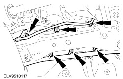
Remove the transaxle cooler line brackets. - Reposition the suction accumulator (A/C), if equipped.
| | | -
CAUTION:Support the subframe using Powertrain Lift. Place wooden block approximately 40 inches in lenght secured to lift under subframe. Remove the sub-frame. | | | -
Remove the right-hand support insulator through bolt. | | | -
CAUTION:Do not loosen connector cooler inlet to transaxle. Remove the upper transaxle cooling tube. - Lock hole with suitable stuffing.
| | | -
CAUTION:Do not loosen connector cooler inlet to transaxle. Remove transaxle cooler lines. - Unclip transaxle cooler line from hold down.
- Lock hole with suitable stuffing.
| | | -
CAUTION:To avoid to damage halfshaft joints and boots, do not bend the inner halfshaft joint by more than 18 degrees, the outer one by not more than 45 degrees. | | | -
Pull out the left-hand halfshaft and tie it up. | | | -
Remove the right-hand halfshaft and intermediate shaft. - Remove the intermediate shaft from the transmission and tie it up together with the front driveshaft.
| | | -
Remove the torque converter rubber and the four torque converter nuts. - Remove rubber cover to gain access to the torque converter nuts.
- Rotate the torque converter to gain access to remaining nuts.
| | | -
Install the transmission jack and CD4E transaxle adaptor. | | | -
Remove the lower bellhousing bolts. | | | -
Remove the front bellhousing bolts. | | | -
Open clamp and disconnect the main control cover vent tube (if available). | |