| Installation Special Tool(s) | | Protector, Halfshaft Seal 205-775 | | | Support Bar, Engine 303-290A (21-140) | | | Adapter for 303-290A 303-290-02 (21-140-02) | | | Adapter for 303-290A 303-290-03 (21-140-03) | | | Adapter for 303-290A 303-290-13 (21-140-09) | General Equipment Materials Name Specification Transmission Fluid WSD-M2C200-C | | -
CAUTION:Do not damage the starter motor seal. With the aid of another technician, use a suitable transmission jack to install the transaxle. | | | -
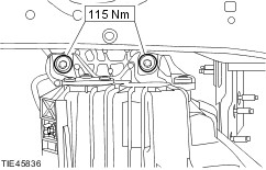
Install the transaxle right-hand retaining bolts. | | | -
Install the transaxle left-hand retaining bolts. | | | -
NOTE:Do not fully tighten the engine and transaxle rear mount bracket retaining bolt at this stage. Install the engine and transaxle rear mount bracket retaining bolt. | | | -
NOTE:Do not fully tighten the engine and transaxle rear mount bracket retaining bolts at this stage. Install the engine and transaxle rear mount bracket retaining bolts. | | | -
Raise and support the vehicle.
For additional information, refer to: Jacking (100-02 Jacking and Lifting, Description and Operation) /
Lifting (100-02 Jacking and Lifting, Description and Operation).
| | | -
Tighten the engine and transaxle rear mount bracket retaining bolt. | | | -
Tighten the engine and transaxle rear mount bracket retaining bolts. | | | -
Raise and support the vehicle.
For additional information, refer to: Jacking (100-02 Jacking and Lifting, Description and Operation) /
Lifting (100-02 Jacking and Lifting, Description and Operation).
| | | -
Check the engine and transaxle rear mount bracket retaining bolt torque. | | | -
Raise the engine and transaxle assembly. | | | -
CAUTION:Carefully install the engine and transaxle rear mount retaining bolts to prevent damage to the threads. NOTE:Install new retaining bolts. NOTE:Do not fully tighten the engine and transaxle rear mount retaining bolts at this stage. Install the engine and transaxle rear mount. | | | -
CAUTION:Visibly inspect that the mount is parallel to the body side member before tightening the retaining nut. If the mount is not parallel loosen the bolts and move the position the engine. Tighten the engine and transaxle rear mount in the sequence shown. | | | -
Raise and support the vehicle.
For additional information, refer to: Jacking (100-02 Jacking and Lifting, Description and Operation) /
Lifting (100-02 Jacking and Lifting, Description and Operation).
| | | -
Install the engine and transaxle rear mount retaining bolts. | | | -
Check the engine and transaxle rear mount retaining nut torque. | | | -
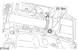
Connect the reversing lamp switch electrical connector. | | | -
Connect the clutch slave cylinder supply line to the transaxle. | | | -
NOTE:When installing the gearshift cables to the transaxle linkage an audible click should be heard when the tabs are correctly seated. Attach the gearshift cables to the transaxle. - Attach the gearshift cables to the bracket and insert the retaining pins.
- Attach the gearshift cables to the transaxle linkage and press the tabs into the ball and socket.
| | | -
Adjust the gearshift cables.
For additional information, refer to: Gearshift Cable Adjustment - Vehicles With: 5-Speed Manual Transmission (VXT-75) (308-00 Manual Transmission/Transaxle and Clutch - General Information, General Procedures).
| | | -
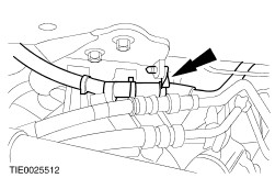
Attach the transaxle vent hose to the transaxle. | | | -
Raise and support the vehicle.
For additional information, refer to: Jacking (100-02 Jacking and Lifting, Description and Operation) /
Lifting (100-02 Jacking and Lifting, Description and Operation).
| | | -
Remove the special tools. | | | -
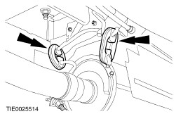
Attach the front muffler hanger insulators to the bracket. | | | -
Attach the exhaust front hanger insulator to the bracket. | | | -
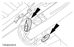
Attach the rear muffler hanger insulators to the bracket. | | | -
Attach the exhaust rear hanger insulator to the bracket. | | | -
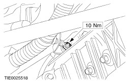
Attach the starter wiring harness retaining bracket to the transaxle. | | | -
Attach the engine wiring harness retaining pin to the retainer. | | | -
Install the heater pipe retaining bracket. | | | -
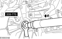
CAUTION:Support the halfshaft. The inner joint must not be bent more than 21 degrees. The outer joint must not be bent more than 45 degrees. CAUTION:Do not damage the halfshaft oil seal. CAUTION:Make sure the snap ring is correctly seated. NOTE:Install a new snap ring. Using the special tool, attach the left-hand halfshaft to the transaxle. | | | -
CAUTION:Support the halfshaft. The inner joint must not be bent more than 21 degrees. The outer joint must not be bent more than 45 degrees. CAUTION:Do not damage the halfshaft oil seal. Using the special tool, attach the right-hand halfshaft to the transaxle. | | | -
NOTE:Install a new halfshaft center bearing cap and locknuts. Install the center bearing cap. | | | -
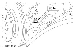
WARNING:Install a new tie-rod end retaining nut. Failure to follow this instruction may result in personal injury. Attach the left-hand tie-rod end to the wheel knuckle. | | | -
WARNING:Install a new lower arm ball joint retaining nut. Failure to follow this instruction may result in personal injury. Attach the lower arms to the wheel knuckles on both sides. | | | -
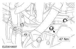
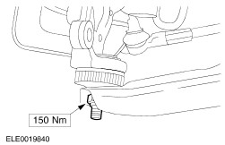
NOTE:Install a new engine support insulator to transaxle retaining bolt. Install the engine support insulator. | | | -
Connect the crankshaft position (CKP) sensor electrical connector. | | | -
Connect the vehicle speed sensor (VSS) electrical connector (if equipped). | | | -
Install the front wheels and tires.
For additional information, refer to: Wheel and Tire (204-04 Wheels and Tires, Removal and Installation).
| | | -
With the vehicle on a level surface, fill the transaxle with transmission fluid until the oil level is just below the bottom of the filler hole. | | | -
Connect the battery ground cable.
For additional information, refer to: Battery Disconnect and Connect (414-01 Battery, Mounting and Cables, General Procedures).
| | |