| Diagnosis and Testing Refer to Wiring Diagrams Section 417-01, for schematic and connector information. Special Tool(s) | | Set of adapter plugs for test probes 29-011A | Inspection and Testing - Verify the customer concern.
- Visually inspect for obvious signs of electrical or mechanical damage.
Visual Inspection Chart | Electrical | - Fuse(s)
- Wiring loom
- Electrical connector(s)
- Switch
| - Resolve any obvious causes or concerns found during the visual inspection before carrying out any further tests.
- If the cause of the concern cannot be found by visual inspection, continue with the symptom chart.
Symptom chart Symptom chart | Symptom | Possible Sources | Action | | Headlamp levelling system inoperative on both sides | * Circuit(s) * Headlight switch * Headlamp * Headlamp leveling motor | * | | Headlamp levelling system inoperative on one side | * Circuit(s) * Headlamp * Headlamp levelling motor. | * | Pinpoint Test NOTE:Use a digital multimeter for all electrical measurements. | PINPOINT TEST A : HEADLAMP LEVELLING SYSTEM INOPERATIVE ON BOTH SIDES | | TEST CONDITIONS | DETAILS/RESULTS/ACTIONS | | A1: NARROW DOWN THE CONDITIONS UNDER WHICH THE FAULT OCCURS | | | 1 Ignition switch in position 0. | | | 2 Disconnect left-hand headlamp. - Box van / Bus / Combi: from connector C1LF08
- Platform truck: from connector CLF08
| | | 3 Disconnect Right-hand headlamp. - Box van / Bus / Combi: from connector C1LF09
- Platform truck, with side light/side turn signal lamp: from connector C1LF09
- Platform truck, without side light/side turn signal lamp: from connector CLF09
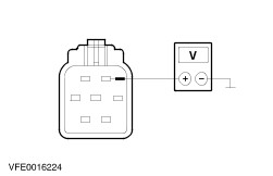
| | | 4 Ignition switch in position II. | | | 5 SWITCH ON the low beam. | | | 6 Measure voltage between the left-hand headlamps: - Box van / Bus / Combi: from connector C1LF08, pin 2, circuit VLF15E (GN), wiring harness side and ground.
- Platform truck, with side light/side turn signal lamp: from connector CLF08, pin 2, circuit VLF15E (GN), wiring harness side and ground.
- Platform truck, without side light/side turn signal lamp: from connector CLF08, pin 2, circuit VLF15C (GN), wiring harness side and ground.
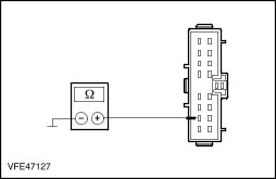
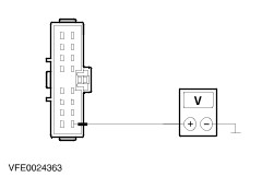
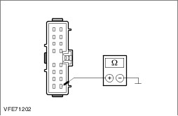
| | | 7 ADJUST the headlamp levelling switch up/down. | | | 8 CHECK test results. | | | When the headlamp levelling system switch is being adjusted, does the voltage level remain constant at battery voltage? Yes No - The voltage changes when the headlamp levelling system switch is adjusted: GO to A5. | | A2: CHECK THE GROUND CONNECTION OF THE HEADLIGHT SWITCH FOR OPEN CIRCUIT | | | 1 Ignition switch in position 0. | | | 2 Disconnect Headlight switch from connector CLF23. | | | 3 Measure the resistance between the headlight switch, connector CLF23, pin 10, circuit B_GD116A (BK/VT), wiring harness side and ground. | | | Is a resistance of less than 2 ohms registered? Yes No LOCATE and RECTIFY the break in the circuit between the headlamp switch and ground connection G16 using the Wiring Diagrams. CHECK system operates correctly | | A3: RULE OUT THE HEADLAMP SWITCH AS THE CAUSE OF THE CONCERN | | | 1 Ignition switch in position II. | | | 2 Measure the voltage between headlamp switch, connector CLF23, pin 1, circuit VLF15A (GN), wiring harness side and ground. | | | Does the meter display battery voltage? Yes LOCATE and RECTIFY short to battery voltage in the circuits connected to soldered connection S2LF15 using the Wiring Diagrams. CHECK system operates correctly No RENEW headlight switch. CHECK system operates correctly | | A4: CHECK THE CONTROL CIRCUITS OF THE HEADLAMP LEVELLING SYSTEM FOR SHORT TO GROUND | | | 1 Ignition switch in position 0. | | | 2 Disconnect Headlight switch from connector CLF23. | | | 3 Measure the resistance between headlamp switch, connector CLF23, pin 1, circuit VLF15A (GN), wiring harness side and ground. | | | Is a resistance of more than 10,000 ohms measured? Yes LOCATE and RECTIFY break in circuit between headlamp switch and soldered connection S2LF15 using the Wiring Diagrams. CHECK system operates correctly No LOCATE and RECTIFY short to ground in the circuits connected to soldered connection S2LF15 using the Wiring Diagrams. CHECK system operates correctly | | A5: EXCLUDE THE HEADLAMP AS THE CAUSE OF THE CONCERN | | | 1 Ignition switch in position 0. | | | 2 Connect Left-hand headlamp:. - Box van / Bus / Combi: to connector C1LF08
- Platform truck: to connector CLF08
| | | 3 Ignition switch in position II. | | | 4 SWITCH ON the low beam. | | | 5 ADJUST the headlamp levelling switch up/down. | | | 6 CHECK left-hand headlamp adjustment. | | | Has the headlamp concerned been adjusted in accordance with the actuation of the headlamp levelling switch? Yes CHECK and if necessary RENEW the right-hand headlamp levelling motor. CHECK system operates correctly No CHECK and if necessary RENEW the left-hand headlamp levelling motor. CHECK system operates correctly | | PINPOINT TEST B : HEADLAMP LEVELLING SYSTEM INOPERATIVE ON ONE SIDE | | TEST CONDITIONS | DETAILS/RESULTS/ACTIONS | | B1: CHECK SIDE LIGHTS ON THE SIDE AFFECTED | | | 1 Ignition switch in position II. | | | 2 SWITCH ON side lights. | | | 3 CHECK front side lamps. | | | Are the front side lamps illuminated? Yes - Left-hand headlamp levelling system inoperative: GO to B2. - Right-hand headlamp levelling system inoperative: GO to B4. No REFER to: Parkleuchten, Rückleuchten, Kennzeichenleuchten (417-01, Diagnosis and Testing). | | B2: CHECK THE CONTROL CIRCUIT OF THE HEADLAMP LEVELLING SYSTEM ON THE LEFT-HAND SIDE FOR OPEN CIRCUIT | | | 1 Ignition switch in position 0. | | | 2 Disconnect left-hand headlamp. - Box van / Bus / Combi: from connector C1LF08
- Platform truck: from connector CLF08
| | | 3 Ignition switch in position II. | | | 4 SWITCH ON the dipped beam. | | | 5 Measure voltage between the left-hand headlamps: - Box van / Bus / Combi: from connector C1LF08, pin 2, circuit VLF15E (GN), wiring harness side and ground.
- Platform truck, with side light/side turn signal lamp: from connector CLF08, pin 2, circuit VLF15E (GN), wiring harness side and ground.
- Platform truck, without side light/side turn signal lamp: from connector CLF08, pin 2, circuit VLF15C (GN), wiring harness side and ground.
| | | 6 CHECK test results. | | | 7 ADJUST the headlamp levelling switch up/down. | | | Does the voltage display change in accordance with the actuation of the headlamp levelling switch? Yes No LOCATE and RECTIFY the break in the circuit between soldered connection S2LF15 and the headlamp using the wiring diagrams. CHECK system operates correctly | | B3: CHECK THE GROUND SUPPLY OF THE HEADLAMP (LEVELLING SYSTEM MOTOR) ON THE LEFT-HAND SIDE FOR OPEN CIRCUIT | | | 1 Ignition switch in position 0. | | | 2 Measure the resistance between the left-hand headlamp: - Box van / Bus / Combi: from connector C1LF08, pin 5, circuit A_GD129U (BK/YE), wiring harness side and ground.
- Platform truck, with side light/side turn signal lamp: from connector CLF08, pin 5, circuit A_GD129U (BK/YE), wiring harness side and ground.
- Platform truck, without side light/side turn signal lamp: from connector CLF08, pin 5, circuit A_GD129D (BK/YE), wiring harness side and ground.
| | | Is a resistance of less than 2 ohms registered? Yes CHECK wiring harness in headlamp for break. If necessary RENEW headlamp levelling motor. CHECK system operates correctly No - Box van / Bus / Combi: LOCATE and RECTIFY the break in the circuit between the headlamp and soldered connection S1D129A using the Wiring Diagrams. CHECK system operates correctly - Platform truck: LOCATE and RECTIFY the break in the circuit between the headlamp and soldered connection S2D129A using the Wiring Diagrams. CHECK system operates correctly | | B4: CHECK THE CONTROL CIRCUIT OF THE HEADLAMP LEVELLING SYSTEM ON THE RIGHT-HAND SIDE FOR OPEN CIRCUIT | | | 1 Ignition switch in position 0. | | | 2 Disconnect Right-hand headlamp. - Box van / Bus / Combi: from connector C1LF09
- Platform truck, with side light/side turn signal lamp: from connector C1LF09
- Platform truck, without side light/side turn signal lamp: from connector CLF09
| | | 3 Ignition switch in position II. | | | 4 SWITCH ON the dipped beam. | | | 5 Measure the voltage at the right-hand headlamp: - Box van / Bus / Combi: Connector C1LF09, pin 2, circuit VLF15F (GN), wiring harness side and ground.
- Platform truck, with side light/side turn signal lamp: Connector C1LF09, pin 2, circuit VLF15F (GN), wiring harness side and ground.
- Platform truck, without side light/side turn signal lamp: from connector CLF09, pin 2, circuit VLF15D (GN), wiring harness side and ground.
| | | 6 CHECK test results. | | | 7 ADJUST the headlamp levelling switch up/down. | | | Does the voltage display change in accordance with the actuation of the headlamp levelling switch? Yes No LOCATE and RECTIFY the break in the circuit between soldered connection S2LF15 and the headlamp using the wiring diagrams. CHECK system operates correctly | | B5: CHECK GROUND CONNECTION OF HEADLAMP (LEVELLING SYSTEM MOTOR) ON THE SIDE AFFECTED FOR BREAKS | | | 1 Ignition switch in position 0. | | | 2 Measure the resistance between the right-hand headlamp: - Box van / Bus / Combi: Connector C1LF09, pin 5, circuit A_GD131W (BK/GY), wiring harness side and ground.
- Platform truck, with side light/side turn signal lamp: Connector C1LF09, pin 5, circuit A_GD131U (BK/GY), wiring harness side and ground.
- Platform truck, without side light/side turn signal lamp: from connector CLF09, pin 5, circuit A_GD131G (BK/GY), wiring harness side and ground.
| | | Is a resistance of less than 2 ohms registered? Yes CHECK wiring harness in headlamp for break. If necessary RENEW headlamp levelling motor. CHECK system operates correctly No LOCATE and RECTIFY the break in the circuit between the headlamp and soldered connection S1D131B using the Wiring Diagrams. CHECK system operates correctly | |