| Diagnosis and Testing Refer to Wiring Diagrams Section 417-02, for schematic and connector information. Inspection and Verification - Verify the customer concern.
- Visually inspect for obvious signs of electrical damage.
Visual Inspection Chart | Electrical | | Fuse(s) | | Wiring harness | | Electrical connector(s) | | Lamp(s) | | Switch(es) | | Central Junction Box (CJB) | - If an obvious cause for an observed or reported concern is found, correct the cause (if possible) before proceeding to the next step.
- If the cause is not visually evident, verify the symptom and refer to the Symptom Chart.
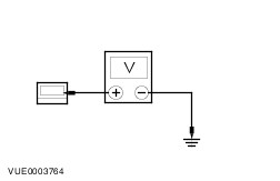
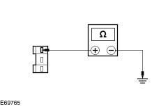
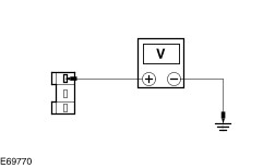
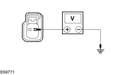
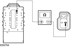
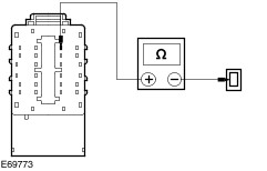
Symptom Chart | Symptom | Possible Sources | Action | | The front interior lamp is inoperative | * Fuse. * Bulb. * Circuit(s). * Interior lamp switch. * Front interior lamp. * CJB. | * | | The second interior lamp is inoperative | * Fuse. * Bulb. * Circuit(s). * Interior lamp switch. * Second interior lamp. * CJB. | * | | First row center interior lamp is inoperative | * Fuse. * Bulb. * Circuit(s). * Interior lamp switch. * Center interior lamp. * CJB. | * | | Second row center interior lamp is inoperative | * Fuse. * Bulb. * Circuit(s). * Interior lamp switch. * Center interior lamp. * CJB. | * | | Third row center interior lamp is inoperative | * Fuse. * Bulb. * Circuit(s). * Interior lamp switch. * Center interior lamp. * CJB. | * | | The left-hand sliding door footwell lamp is inoperative | * Fuse. * Bulb. * Circuit(s). * Footwell lamp switch. * Footwell lamp. * CJB. | * | | The right-hand sliding door footwell lamp is inoperative | * Fuse. * Bulb. * Circuit(s). * Footwell lamp switch. * Footwell lamp. * CJB. | * | | The rear door footwell lamp is inoperative | * Fuse. * Bulb. * Circuit(s). * Footwell lamp switch. * Footwell lamp. * CJB. | * | | The cargo lamp in inoperative (Tourneo) | * Fuse. * Bulb. * Circuit(s). * Cargo lamp switch. * Cargo lamp. * CJB. | * | | The interior lamps do not turn on with one door open | * Fuse. * Circuit(s). * Interior lamp switch. * CJB. | * For front door, GO to Pinpoint Test A. * For left-hand sliding door, GO to Pinpoint Test F. * For right-hand sliding door, GO to Pinpoint Test G. * For rear door/liftgate, GO to Pinpoint Test H. | | The interior lamp does not automatically turn off after 10 minutes when the lamp is in the ILLUMINATED ENTRY position (if equipped) | * Circuit. * CJB. | * CHECK circuit SBP72 (VT/RD) for short to ground. If the circuit is OK, INSTALL a new CJB. TEST the system for normal operation. | | The interior lamp does not automatically turn off after 30 minutes when the lamp is in the ON position (if equipped) | * CJB. | * INSTALL a new CJB. TEST the system for normal operation. | Pinpoint Tests NOTE:Use a digital multimeter for all electrical measurements. | PINPOINT TEST A : THE FRONT INTERIOR LAMP IS INOPERATIVE | | TEST CONDITIONS | DETAILS/RESULTS/ACTIONS | | A1: CHECK THE OPERATION OF THE FRONT INTERIOR LAMP | | | 1 Check the operation of the front interior lamp in both the ON and ILLUMINATED ENTRY positions (if equipped). | | | Is the front interior lamp inoperative in both positions? Yes No If inoperative in the ILLUMINATED ENTRY position from the left-hand front door (chassis cab with manual locking). GO to A4. If inoperative in the ILLUMINATED ENTRY position from the right-hand front door (chassis cab with manual locking). GO to A6. If inoperative in the ILLUMINATED ENTRY position from the driver door (all except chassis cab with manual locking). GO to A8. If inoperative in the ILLUMINATED ENTRY position from the passenger door (all except chassis cab with manual locking). GO to A12. | | A2: CHECK THE FRONT INTERIOR LAMP FOR POWER | | | 1 Disconnect Front Interior Lamp CLN28B. | | | 2 Measure the voltage between the front interior lamp CLN28B pin 1, circuit SBP72 (VT/RD), harness side and ground. | | | Is the voltage greater than 10 volts? Yes No REPAIR circuit SBP72 (VT/RD). TEST the system for normal operation. | | A3: CHECK THE FRONT INTERIOR LAMP FOR GROUND | | | 1 Disconnect Front Interior Lamp CLN28A. | | | 2 Measure the resistance between: - the front interior lamp CLN28A pin 1, circuit GD151 (BK/GN), harness side and ground (all except chassis cab).
- the front interior lamp CLN28A pin 1, circuit GD138 (BK/WH), harness side and ground (chassis cab only).
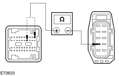
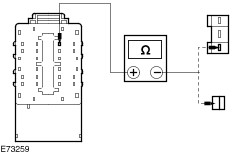
| | | Is the resistance less than 1 ohm? Yes INSTALL a new front interior lamp. TEST the system for normal operation. No REPAIR circuit GD151D (BK/GN) or circuit GD138 (BK/WH) as necessary. TEST the system for normal operation. | | A4: CHECK CIRCUIT CPL01 (VT/GN) FOR OPEN CIRCUIT - LEFT-HAND FRONT DOOR (CHASSIS CAB WITH MANUAL LOCKING ONLY) | | | 1 Disconnect Front Interior Lamp CLN28A. | | | 2 Disconnect Left-Hand Front Door Switch CPL26. | | | 3 Measure the resistance between the front interior lamp CLN28A pin 3, circuit CPL01 (VT/GN), harness side and the left-hand front door switch CPL26 pin 1, circuit CPL01 (VT/GN), harness side. | | | Is the resistance less than 1 ohm? Yes No REPAIR the circuit. TEST the system for normal operation. | | A5: CHECK THE LEFT-HAND FRONT DOOR SWITCH FOR GROUND (CHASSIS CAB WITH MANUAL LOCKING ONLY) | | | 1 Measure the resistance between the left-hand front door switch CPL26 pin 2, circuit GD133 (BK), harness side and ground. | | | Is the resistance less than 1 ohm? Yes INSTALL a new left-hand front door switch No REPAIR circuit GD133 (BK). TEST the system for normal operation. | | A6: CHECK CIRCUIT CPL01 (VT/GN) FOR OPEN CIRCUIT - RIGHT-HAND FRONT DOOR (CHASSIS CAB WITH MANUAL LOCKING ONLY) | | | 1 Disconnect CJB CBP02C. | | | 2 Disconnect Left-Hand Front Door Switch CPL31. | | | 3 Measure the resistance between the CJB CBP02C pin 14, circuit CPL01 (VT/GN), harness side and the right-hand front door switch CPL31 pin 1, circuit CPL01 (VT/GN), harness side. | | | Is the resistance less than 1 ohm? Yes No REPAIR the circuit. TEST the system for normal operation. | | A7: CHECK THE RIGHT-HAND FRONT DOOR SWITCH FOR GROUND (CHASSIS CAB WITH MANUAL LOCKING ONLY) | | | 1 Measure the resistance between the right-hand front door switch CPL31 pin 2, circuit GD138 (BK/WH), harness side and ground | | | Is the resistance less than 1 ohm? Yes INSTALL a new right-hand front door switch No REPAIR circuit GD138 (BK/WH). TEST the system for normal operation. | | A8: CHECK CIRCUIT CLN03 (YE/GY) FOR OPEN CIRCUIT - DRIVER DOOR (ALL EXCEPT CHASSIS CAB WITH MANUAL LOCKING) | | | 1 Disconnect CJB CBP02B. | | | 2 Disconnect Front Interior Lamp CLN28A. | | | 3 Measure the resistance between the front interior lamp CLN28A pin 3, circuit CLN03 (YE/GY), harness side and the CJB CBP02B pin 22, circuit CLN03 (YE/GY), harness side. | | | Is the resistance less than 1 ohm? Yes No REPAIR the circuit. TEST the system for normal operation. | | A9: CHECK THE FRONT INTERIOR LAMP CIRCUIT FOR GROUND WITH THE DRIVER DOOR OPEN AND CLOSED (ALL EXCEPT CHASSIS CAB WITH MANUAL LOCKING) | | | 1 Disconnect CJB CBP02C. | | | 2 Measure the resistance between: - (LHD) the CJB CBP02C pin 14, circuit CPL26 (GN/VT), harness side and ground with the driver door closed and the driver door open.
- (RHD) the CJB CBP02C pin 1, circuit CPL31 (WH), harness side and ground with the driver door closed and the driver door open.
| | | Is the resistance less than 1 ohm with the driver door closed and greater than 10,000 ohms with the driver door open? Yes INSTALL a new CJB. TEST the system for normal operation. No | | A10: CHECK CIRCUIT CPL26 (GN/VT) OR CIRCUIT CPL31 (GN/BK) - DRIVER DOOR FOR OPEN CIRCUIT (ALL EXCEPT CHASSIS CAB WITH MANUAL LOCKING) | | | 1 Disconnect Driver Door Latch CPL22. | | | 2 Measure the resistance between: - (LHD) the CJB CBP02C pin 14, circuit CPL26 (GN/VT), harness side and the driver door latch CPL22 pin 8, circuit CPL26 (GN/VT), harness side.
- (RHD) the CJB CBP02C pin 1, circuit CPL31 (GN/BK), harness side and the driver door latch CPL22 pin 8, circuit CPL31 (GN/BK), harness side.
| | | Is the resistance less than 1 ohm? Yes No REPAIR circuit CPL26 (GN/VT) or circuit CPL31 (GN/BK) as necessary. TEST the system for normal operation. | | A11: CHECK THE DRIVER DOOR LATCH FOR GROUND (ALL EXCEPT CHASSIS CAB WITH MANUAL LOCKING) | | | 1 Measure the resistance between: - the driver door latch CPL22 pin 6, circuit GD133 (BK), harness side and ground (Jumbo).
- the driver door latch CPL22 pin 6, circuit GD138 (BK/WH), harness side and ground (Tourneo).
- the driver door latch CPL22 pin 6, circuit GD138 (BK/WH), harness side and ground (Chassis cab with power locking).
| | | Is the resistance less than 1 ohm? Yes INSTALL a new driver door latch.
REFER to: Front Door Latch (501-14 Handles, Locks, Latches and Entry Systems, Removal and Installation).
TEST the system for normal operation. If the concern persists, INSTALL a new CJB. TEST the system for normal operation. No REPAIR circuit GD133 (BK) or circuit GD138 (BK/WH) as necessary. TEST the system for normal operation. | | A12: CHECK CIRCUIT CLN03 (YE/GY) FOR OPEN CIRCUIT (ALL EXCEPT CHASSIS CAB WITH MANUAL LOCKING) | | | 1 Disconnect CJB CBP02B. | | | 2 Disconnect Front Interior Lamp CLN28A. | | | 3 Measure the resistance between the front interior lamp CLN28A pin 3, circuit CLN03 (YE/GY), harness side and the CJB CBP02B pin 22, circuit CLN03 (YE/GY), harness side. | | | Is the resistance less than 1 ohm? Yes No REPAIR the circuit. TEST the system for normal operation. | | A13: CHECK THE FRONT INTERIOR LAMP CIRCUIT FOR GROUND WITH THE PASSENGER DOOR OPEN AND CLOSED (ALL EXCEPT CHASSIS CAB WITH MANUAL LOCKING) | | | 1 Disconnect CJB CBP02C. | | | 2 Measure the resistance between: - (LHD) the CJB CBP02C pin 1, circuit CPL31 (WH), harness side and ground with the passenger door closed and the passenger door open.
- (RHD) the CJB CBP02C pin 14, circuit CPL26 (GN/VT), harness side and ground with the passenger door closed and the passenger door open.
| | | Is the resistance less than 5 ohms with the passenger door closed and greater that 10,000 ohms with the passenger door open? Yes INSTALL a new CJB. TEST the system for normal operation. No | | A14: CHECK CIRCUIT CPL26 (GN/VT) OR CIRCUIT CPL31 (WH) FOR OPEN CIRCUIT (ALL EXCEPT CHASSIS CAB WITH MANUAL LOCKING) | | | 1 Disconnect Passenger Door Latch CPL22. | | | 2 Measure the resistance between: - (LHD) the CJB CBP02C pin 14, circuit CPL26 (GN/VT), harness side and the passenger door latch CPL22 pin 8, circuit CPL26 (GN/VT), harness side.
- (RHD) the CJB CBP02C pin 1, circuit CPL31 (WH), harness side and the passenger door latch CPL22 pin 8, circuit CPL31 (WH), harness side.
| | | Is the resistance less than 1 ohm? Yes No REPAIR circuit CPL31 (WH) or circuit CPL26 (GN/VT). TEST the system for normal operation. | | A15: CHECK THE PASSENGER DOOR LATCH FOR GROUND (ALL EXCEPT CHASSIS CAB WITH MANUAL LOCKING) | | | 1 Measure the resistance between: - the passenger door latch CPL22 pin 6, circuit GD138 (BK/WH), harness side and ground (Jumbo).
- the passenger door latch CPL22 pin 6, circuit GD133 (BK), harness side and ground (Tourneo).
- the passenger door latch CPL22 pin 6, circuit GD133 (BK), harness side and ground (Chassis cab with power locking).
| | | Is the resistance less than 1 ohm? Yes INSTALL a new passenger door latch.
REFER to: Front Door Latch (501-14 Handles, Locks, Latches and Entry Systems, Removal and Installation).
TEST the system for normal operation. If the concern persists, INSTALL a new CJB. TEST the system for normal operation. No REPAIR circuit GD133 (BK) or circuit GD138 (BK/WH) as necessary. TEST the system for normal operation. | | PINPOINT TEST B : THE SECOND INTERIOR LAMP IS INOPERATIVE | | TEST CONDITIONS | DETAILS/RESULTS/ACTIONS | | B1: CHECK THE OPERATION OF THE SECOND INTERIOR LAMP | | | 1 Check the operation of the second interior lamp in both the ON and ILLUMINATED ENTRY positions (if equipped). | | | Is the second interior lamp inoperative in both positions? Yes No If inoperative in the ILLUMINATED ENTRY position from the left-hand front door (chassis cab with manual locking). GO to B4. If inoperative in the ILLUMINATED ENTRY position from the right-hand front door (chassis cab with manual locking). GO to B6. If inoperative in the ILLUMINATED ENTRY position from the driver door (all except chassis cab with manual locking). GO to B8. If inoperative in the ILLUMINATED ENTRY position from the passenger door (all except chassis cab with manual locking). GO to B12. | | B2: CHECK THE SECOND INTERIOR LAMP FOR POWER | | | 1 Disconnect Second Interior Lamp CLN28D. | | | 2 Measure the voltage between the second interior lamp CLN28D pin 1, circuit SBP72 (VT/RD), harness side and ground. | | | Is the voltage greater than 10 volts? Yes No REPAIR circuit SBP72 (VT/RD). TEST the system for normal operation. | | B3: CHECK THE SECOND INTERIOR LAMP FOR GROUND | | | 1 Disconnect Second Interior Lamp CLN28C. | | | 2 Measure the resistance between: - the second interior lamp CLN28C pin 1, circuit GD151 (BK/GN), harness side and ground (all except chassis cab).
- the second interior lamp CLN28C pin 1, circuit GD138 (BK/WH), harness side and ground (chassis cab only).
| | | Is the resistance less than 1 ohm? Yes INSTALL a new second interior lamp. TEST the system for normal operation. No REPAIR circuit GD151 (BK/GN) or circuit GD138 (BK/WH). TEST the system for normal operation. | | B4: CHECK CIRCUIT CPL01 (VT/GN) FOR OPEN CIRCUIT - LEFT-HAND FRONT DOOR (CHASSIS CAB WITH MANUAL LOCKING ONLY) | | | 1 Disconnect Second Interior Lamp CLN28C. | | | 2 Disconnect Left-Hand Front Door Switch CPL26. | | | 3 Measure the resistance between the second interior lamp CLN28C pin 3, circuit CPL01 (VT/GN), harness side and the left-hand front door switch CPL26 pin 1, circuit CPL01 (VT/GN), harness side. | | | Is the resistance less than 1 ohm? Yes No REPAIR the circuit. TEST the system for normal operation. | | B5: CHECK THE LEFT-HAND FRONT DOOR SWITCH FOR GROUND (CHASSIS CAB WITH MANUAL LOCKING ONLY) | | | 1 Measure the resistance between the left-hand front door switch CPL26 pin 2, circuit GD133 (BK), harness side and ground. | | | Is the resistance less than 1 ohm? Yes INSTALL a new left-hand front door switch No REPAIR circuit GD133 (BK). TEST the system for normal operation. | | B6: CHECK CIRCUIT CPL01 (VT/GN) FOR OPEN CIRCUIT - RIGHT-HAND FRONT DOOR (CHASSIS CAB WITH MANUAL LOCKING ONLY) | | | 1 Disconnect CJB CBP02C. | | | 2 Disconnect Left-Hand Front Door Switch CPL31. | | | 3 Measure the resistance between the CJB CBP02C pin 14, circuit CPL01 (VT/GN), harness side and the right-hand front door switch CPL31 pin 1, circuit CPL01 (VT/GN), harness side. | | | Is the resistance less than 1 ohm? Yes No REPAIR the circuit. TEST the system for normal operation. | | B7: CHECK THE RIGHT-HAND FRONT DOOR SWITCH FOR GROUND (CHASSIS CAB WITH MANUAL LOCKING ONLY) | | | 1 Measure the resistance between the right-hand front door switch CPL31 pin 2, circuit GD138 (BK/WH), harness side and ground | | | Is the resistance less than 1 ohm? Yes INSTALL a new right-hand front door switch No REPAIR circuit GD138 (BK/WH). TEST the system for normal operation. | | B8: CHECK CIRCUIT CLN03 (YE/GY) FOR OPEN CIRCUIT - DRIVER DOOR (ALL EXCEPT CHASSIS CAB WITH MANUAL LOCKING) | | | 1 Disconnect CJB CBP02B. | | | 2 Disconnect Second Interior Lamp CLN28C. | | | 3 Measure the resistance between the second interior lamp CLN28C pin 3, circuit CLN03 (YE/GY), harness side and the CJB CBP02B pin 22, circuit CLN03 (YE/GY), harness side. | | | Is the resistance less than 5 ohms? Yes No REPAIR the circuit. TEST the system for normal operation. | | B9: CHECK THE SECOND INTERIOR LAMP CIRCUIT FOR GROUND WITH THE DRIVER DOOR OPEN AND CLOSED (ALL EXCEPT CHASSIS CAB WITH MANUAL LOCKING) | | | 1 Disconnect CJB CBP02C. | | | 2 Measure the resistance between: - (LHD) the CJB CBP02C pin 14, circuit CPL26 (GN/VT), harness side and ground with the driver door closed and the driver door open.
- (RHD) the CJB CBP02C pin 1, circuit CPL31 (GN/BK), harness side and ground with the driver door closed and the driver door open.
| | | Is the resistance less than 1 ohm with the driver door closed and greater that 10,000 ohms with the driver door open? Yes INSTALL a new CJB. TEST the system for normal operation. No | | B10: CHECK CIRCUIT CPL26 (GN/VT) OR CIRCUIT CPL31 (GN/BK) - DRIVER DOOR FOR OPEN CIRCUIT (ALL EXCEPT CHASSIS CAB WITH MANUAL LOCKING) | | | 1 Disconnect Driver Door Latch CPL22. | | | 2 Measure the resistance between: - (LHD) the CJB CBP02C pin 14, circuit CPL26 (GN/VT), harness side and the driver door latch CPL22 pin 8, circuit CPL26 (GN/VT), harness side.
- (RHD) the CJB CBP02C pin 1, circuit CPL31 (GN/BK), harness side and the driver door latch CPL22 pin 8, circuit CPL31 (GN/BK), harness side.
| | | Is the resistance less than 1 ohm? Yes No REPAIR circuit CPL26 (GN/VT) or circuit CPL31 (GN/BK) as necessary. TEST the system for normal operation. | | B11: CHECK THE DRIVER DOOR LATCH FOR GROUND (ALL EXCEPT CHASSIS CAB WITH MANUAL LOCKING) | | | 1 Measure the resistance between: - the driver door latch CPL22 pin 6, circuit GD133 (BK), harness side and ground (Jumbo).
- the driver door latch CPL22 pin 6, circuit GD138 (BK/WH), harness side and ground (Tourneo).
- the driver door latch CPL22 pin 6, circuit GD138 (BK/WH), harness side and ground (Chassis cab with power locking).
| | | Is the resistance less than 1 ohm? Yes INSTALL a new driver door latch.
REFER to: Front Door Latch (501-14 Handles, Locks, Latches and Entry Systems, Removal and Installation).
TEST the system for normal operation. If the concern persists, INSTALL a new CJB. TEST the system for normal operation. No REPAIR circuit GD133 (BK) or circuit GD138 (BK/WH) as necessary. TEST the system for normal operation. | | B12: CHECK CIRCUIT CLN03 (YE/GY) FOR OPEN CIRCUIT (ALL EXCEPT CHASSIS CAB WITH MANUAL LOCKING) | | | 1 Disconnect CJB CBP02B. | | | 2 Disconnect Second Interior Lamp CLN28C. | | | 3 Measure the resistance between the second interior lamp CLN28C pin 3, circuit CLN03 (YE/GY), harness side and the CJB CBP02B pin 22, circuit CLN03 (YE/GY), harness side. | | | Is the resistance less than 1 ohm? Yes No REPAIR the circuit. TEST the system for normal operation. | | B13: CHECK THE SECOND INTERIOR LAMP CIRCUIT FOR GROUND WITH THE PASSENGER DOOR OPEN AND CLOSED (ALL EXCEPT CHASSIS CAB WITH MANUAL LOCKING) | | | 1 Disconnect CJB CBP02C. | | | 2 Measure the resistance between: - (LHD) the CJB CBP02C pin 1, circuit CPL31 (WH), harness side and ground with the passenger door closed and the passenger door open.
- (RHD) the CJB CBP02C pin 14, circuit CPL26 (GN/VT), harness side and ground with the passenger door closed and the passenger door open.
| | | Is the resistance less than 1 ohm with the passenger door closed and greater that 10,000 ohms with the passenger door open? Yes INSTALL a new CJB. TEST the system for normal operation. No | | B14: CHECK CIRCUIT CPL26 (GN/VT) OR CIRCUIT CPL31 (WH) FOR OPEN CIRCUIT (ALL EXCEPT CHASSIS CAB WITH MANUAL LOCKING) | | | 1 Disconnect Passenger Door Latch CPL22. | | | 2 Measure the resistance between: - (LHD) the CJB CBP02C pin 14, circuit CPL26 (GN/VT), harness side and the passenger door latch CPL22 pin 8, circuit CPL26 (GN/VT), harness side.
- (RHD) the CJB CBP02C pin 1, circuit CPL31 (WH), harness side and the passenger door latch CPL22 pin 8, circuit CPL31 (WH), harness side.
| | | Is the resistance less than 1 ohm? Yes No REPAIR circuit CPL31 (WH) or cicuit CPL26 (GN/VT). TEST the system for normal operation. | | B15: CHECK THE PASSENGER DOOR LATCH FOR GROUND (ALL EXCEPT CHASSIS CAB WITH MANUAL LOCKING) | | | 1 Measure the resistance between: - the passenger door latch CPL22 pin 6, circuit GD138 (BK/WH), harness side and ground (Jumbo).
- the passenger door latch CPL22 pin 6, circuit GD133 (BK), harness side and ground (Tourneo).
- the passenger door latch CPL22 pin 6, circuit GD133 (BK), harness side and ground (Chassis cab with power locking).
| | | Is the resistance less than 1 ohm? Yes INSTALL a new passenger door latch.
REFER to: Front Door Latch (501-14 Handles, Locks, Latches and Entry Systems, Removal and Installation).
TEST the system for normal operation. If the concern persists, INSTALL a new CJB. TEST the system for normal operation. No REPAIR circuit GD133 (BK) or circuit GD138 (BK/WH) as necessary. TEST the system for normal operation. | | PINPOINT TEST C : FIRST ROW CENTER INTERIOR LAMP IS INOPERATIVE | | TEST CONDITIONS | DETAILS/RESULTS/ACTIONS | | C1: CHECK THE FIRST ROW CENTER INTERIOR LAMP FOR POWER | | | 1 Disconnect First Row Center Interior Lamp CLN28E. | | | 2 Measure the voltage between the first row center interior lamp CLN28E pin 1, circuit SBP72 (VT/RD), harness side and ground. | | | Is the voltage greater than 10 volts? Yes No REPAIR circuit SBP72 (VT/RD). TEST the system for normal operation. | | C2: CHECK CIRCUIT CLN43 FOR OPEN CIRCUIT | | | 1 Disconnect First Row Center Interior Lamp CLN28F. | | | 2 Disconnect CJB CBP02B. | | | 3 Measure the resistance between the first row center interior lamp CLN28F pin 1, circuit CLN43 (WH/BU), harness side and the CJB CBP02B pin 27, circuit CLN43 (WH/BU), harness side. | | | Is the resistance less than 1 ohm? Yes INSTALL a new first row center interior lamp. TEST the system for normal operation. If the concern persists, INSTALL a new CJB. TEST the system for normal operation. No REPAIR circuit CLN43 (WH/BU). TEST the system for normal operation. | | PINPOINT TEST D : SECOND ROW CENTER INTERIOR LAMP IS INOPERATIVE | | TEST CONDITIONS | DETAILS/RESULTS/ACTIONS | | D1: CHECK THE SECOND ROW CENTER INTERIOR LAMP FOR POWER | | | 1 Disconnect Second Row Center Interior Lamp CLN28G (Jumbo). | | | 2 Disconnect Second Row Center Interior Lamp CLN28F (Tourneo). | | | 3 Measure the voltage between: - the second row center interior lamp CLN28G pin 1, circuit SBP72 (VT/RD), harness side and ground (Jumbo).
- the second row center interior lamp CLN28F pin 1, circuit SBP72 (VT/RD), harness side and ground (Tourneo).
| | | Is the voltage greater than 10 volts? Yes No REPAIR circuit SBP72 (VT/RD). TEST the system for normal operation. | | D2: CHECK THE SECOND ROW CENTER INTERIOR LAMP FOR GROUND | | | 1 Measure the resistance between the second row center interior lamp CLN28E pin 1, circuit GD151 (BK/GN), harness side and ground. | | | Is the resistance less than 1 ohm? Yes No REPAIR circuit GD151 (BK/GN). TEST the system for normal operation. | | D3: CHECK CIRCUIT CLN43 (WH/BU) FOR OPEN CIRCUIT | | | 1 Disconnect Second Row Center Interior Lamp CLN28H (Jumbo). | | | 2 Disconnect Second Row Center Interior Lamp CLN28E (Tourneo). | | | 3 Disconnect CJB CBP02B. | | | 4 Measure the resistance between: - the second row center interior lamp CLN28H pin 1, circuit CLN43 , harness side and the CJB CBP02B pin 27, circuit CLN43 (WH/BU), harness side (Jumbo).
- the second row center interior lamp CLN28H pin 3, circuit CLN43 (WH/BU), harness side and the CJB CBP02B pin 27, circuit CLN43 (WH/BU), harness side (Tourneo).
| | | Is the resistance less than 1 ohm? Yes INSTALL a new second row center interior lamp. TEST the system for normal operation. If the concern persists, INSTALL a new CJB. TEST the system for normal operation. No REPAIR circuit CLN43 (WH/BU). TEST the system for normal operation. | | PINPOINT TEST E : THIRD ROW CENTER INTERIOR LAMP IS INOPERATIVE | | TEST CONDITIONS | DETAILS/RESULTS/ACTIONS | | E1: CHECK THE THIRD ROW CENTER INTERIOR LAMP FOR POWER | | | 1 Disconnect Third Row Center Interior Lamp CLN28J (Jumbo). | | | 2 Disconnect Third Row Center Interior Lamp CLN28H (Tourneo). | | | 3 Measure the voltage between: - the third row center interior lamp CLN28J pin 1, circuit SBP72 (VT/RD), harness side and ground.
- the third row center interior lamp CLN28H pin 1, circuit SBP72 (VT/RD), harness side and ground.
| | | Is the voltage greater than 10 volts? Yes No REPAIR circuit SBP72 (VT/RD). TEST the system for normal operation. | | E2: CHECK THE THIRD ROW CENTER INTERIOR LAMP FOR GROUND | | | 1 Measure the resistance between the third row center interior lamp CLN28G pin 1, circuit GD151 (BK/GN), harness side and ground (Tourneo). | | | Is the resistance less than 1 ohm? Yes No REPAIR circuit GD151 (BK/GN). TEST the system for normal operation. | | E3: CHECK CIRCUIT CLN43 (WH/BU) FOR OPEN CIRCUIT | | | 1 Disconnect Third Row Center Interior Lamp CLN28K (Jumbo). | | | 2 Disconnect Third Row Center Interior Lamp CLN28G (Tourneo). | | | 3 Disconnect CJB CBP02B. | | | 4 Measure the resistance between: - the third row center interior lamp CLN28K pin 1, circuit CLN43 (WH/BU), harness side and the CJB CBP02B pin 27, circuit CLN43 (WH/BU), harness side (Jumbo).
- the third row center interior lamp CLN28G pin 1, circuit CLN43 (WH/BU), harness side and the CJB CBP02B pin 27, circuit CLN43 (WH/BU), harness side (Tourneo).
| | | Is the resistance less than 1 ohm? Yes INSTALL a new third row center interior lamp. TEST the system for normal operation. If the concern persists, INSTALL a new CJB. TEST the system for normal operation. No REPAIR circuit CLN43 (WH/BU). TEST the system for normal operation. | | PINPOINT TEST F : THE LEFT-HAND SLIDING DOOR FOOTWELL LAMP IS INOPERATIVE | | TEST CONDITIONS | DETAILS/RESULTS/ACTIONS | | F1: CHECK THE LEFT-HAND SLIDING DOOR FOOTWELL LAMP FOR POWER | | | 1 Disconnect Left-Hand Sliding Door Footwell Lamp CLN28N. | | | 2 Measure the voltage between the left-hand sliding door footwell lamp CLN28N pin 1, circuit SBP72 (VT/RD), harness side and ground. | | | Is the voltage greater than 10 volts? Yes No REPAIR circuit SBP72 (VT/RD). TEST the system for normal operation. | | F2: CHECK CIRCUIT CLN43 (WH/BU) FOR OPEN CIRCUIT | | | 1 Disconnect Left-Hand Sliding Door Footwell Lamp CLN28P. | | | 2 Disconnect CJB CBP02B. | | | 3 Measure the resistance between the left-hand sliding door footwell lamp CLN28P pin 1, circuit CLN43 (WH/BU), harness side and the CJB CBP02B pin 27, circuit CLN43 (WH/BU), harness side. | | | Is the resistance less than 1 ohm? Yes INSTALL a new left-hand sliding door footwell lamp. TEST the system for normal operation. If the concern persists, GO to F3. No REPAIR circuit CLN43 (WH/BU). TEST the system for normal operation. | | F3: CHECK THE LEFT-HAND SLIDING DOOR SWITCH FOR POWER | | | 1 Disconnect Left-Hand Sliding Door Switch CPL36D. | | | 2 Measure the voltage between the left-hand sliding door switch CPL36D pin 1, circuit CPL36 (GN), harness side and ground. | | | Is the voltage greater than 10 volts? Yes No REPAIR circuit CPL36 (GN). TEST the system for normal operation. | | F4: CHECK THE LEFT-HAND SLIDING DOOR SWITCH FOR GROUND | | | 1 Measure the resistance between the left-hand sliding door switch CPL36D pin 2, circuit GD149 (BK/GY), harness side and ground. | | | Is the resistance less than 1 ohm? Yes INSTALL a new left-hand sliding door switch. TEST the system for normal operation. If the concern persists, INSTALL a new CJB. TEST the system for normal operation. No REPAIR circuit GD149 (BK/GY). TEST the system for normal operation. | | PINPOINT TEST G : THE RIGHT-HAND SLIDING DOOR FOOTWELL LAMP IS INOPERATIVE | | TEST CONDITIONS | DETAILS/RESULTS/ACTIONS | | G1: CHECK THE RIGHT-HAND SLIDING DOOR FOOTWELL LAMP FOR POWER | | | 1 Disconnect Right-Hand Sliding Door Footwell Lamp CLN28Q. | | | 2 Measure the voltage between the right-hand sliding door footwell lamp CLN28Q pin 1, circuit SBP72AD (VT/RD), harness side and ground. | | | Is the voltage greater than 10 volts? Yes No REPAIR circuit SBP72AD (VT/RD). TEST the system for normal operation. | | G2: CHECK CIRCUIT CLN43 (WH/BU) FOR OPEN CIRCUIT | | | 1 Disconnect Right-Hand Sliding Door Footwell Lamp CLN28R. | | | 2 Disconnect CJB CBP02B. | | | 3 Measure the resistance between the right-hand sliding door footwell lamp CLN28R pin 1, circuit CLN43 (WH/BU), harness side and the CJB CBP02B pin 27, circuit CLN43 (WH/BU), harness side. | | | Is the resistance less than 5 ohms? Yes INSTALL a new right-hand sliding door footwell lamp. TEST the system for normal operation. If the concern persists, GO to G3. No REPAIR circuit CLN43 (WH/BU). TEST the system for normal operation. | | G3: CHECK THE RIGHT-HAND SLIDING DOOR SWITCH FOR POWER | | | 1 Disconnect Right-Hand Sliding Door Switch CPL39D. | | | 2 Measure the voltage between the right-hand sliding door switch CPL39D pin 1, circuit CPL39 (YE), harness side and ground. | | | Is the voltage greater than 10 volts? Yes No REPAIR circuit CPL39 (YE). TEST the system for normal operation. | | G4: CHECK THE RIGHT-HAND SLIDING DOOR SWITCH FOR GROUND | | | 1 Measure the resistance between the right-hand sliding door switch CPL39D pin 2, circuit GD151 (BK/GN), harness side and ground. | | | Is the resistance less than 1 ohm? Yes INSTALL a new right-hand sliding door switch. TEST the system for normal operation. If the concern persists, INSTALL a new CJB. TEST the system for normal operation. No REPAIR circuit GD149 (BK/GY). TEST the system for normal operation. | | PINPOINT TEST H : THE REAR DOOR FOOTWELL LAMP IS INOPERATIVE | | TEST CONDITIONS | DETAILS/RESULTS/ACTIONS | | H1: CHECK THE REAR DOOR FOOTWELL LAMP FOR POWER | | | 1 Disconnect Rear Door Footwell Lamp CLN28L. | | | 2 Measure the voltage between the rear door footwell lamp CLN28L pin 1, circuit SBP72 (VT/RD), harness side and ground. | | | Is the voltage greater than 10 volts? Yes No REPAIR circuit SBP72 (VT/RD). TEST the system for normal operation. | | H2: CHECK CIRCUIT CLN43 (WH/BU) FOR OPEN CIRCUIT | | | 1 Disconnect Rear Door Footwell Lamp CLN28M. | | | 2 Disconnect CJB CBP02B. | | | 3 Measure the resistance between the rear door footwell lamp CLN28M pin 1, circuit CLN43 (WH/BU), harness side and the CJB CBP02B pin 27, circuit CLN43 (WH/BU), harness side. | | | Is the resistance less than 1 ohm? Yes INSTALL a new rear door footwell lamp. TEST the system for normal operation. If the concern persists, INSTALL a new CJB. TEST the system for normal operation. No REPAIR circuit CLN43 . TEST the system for normal operation. | | PINPOINT TEST I : THE CARGO LAMP IS INOPERATIVE (TOURNEO) | | TEST CONDITIONS | DETAILS/RESULTS/ACTIONS | | I1: CHECK THE CARGO LAMP FOR POWER | | | 1 Disconnect Cargo Lamp CLN28K. | | | 2 Measure the voltage between the cargo lamp CLN28K pin 1, circuit SBP72 (VT/RD), harness side and ground. | | | Is the voltage greater than 10 volts? Yes No REPAIR circuit SBP72 (VT/RD). TEST the system for normal operation. | | I2: CHECK THE CARGO LAMP FOR GROUND | | | 1 Disconnect Cargo Lamp CLN28J. | | | 2 Measure the resistance between the cargo lamp CLN28J pin 1, circuit GD151 (BK/GN), harness side and ground. | | | Is the resistance less than 1 ohm? Yes No REPAIR circuit GD151 (BK/GN). TEST the system for normal operation. | | I3: CHECK CIRCUIT CLN43 (WH/BU) FOR OPEN CIRCUIT | | | 1 Measure the resistance between the cargo lamp CLN28J pin 3, circuit CLN43 (WH/BU), harness side and the CJB CBP02B pin 27, circuit CLN43 (WH/BU), harness side. | | | Is the resistance less than 1 ohm? Yes INSTALL a new cargo lamp. TEST the system for normal operation. If the concern persists, GO to I4. No REPAIR circuit CLN43 (WH/BU). TEST the system for normal operation. | | I4: CHECK THE REAR DOOR LATCH FOR POWER | | | 1 Disconnect Rear Door Latch CPL44. | | | 2 Measure the voltage between the rear door latch CPL44 pin 8, circuit CPL44 (YE/OG), harness side and ground. | | | Is the voltage greater than 10 volts? Yes No REPAIR circuit CPL44 (YE/OG). TEST the system for normal operation. | | I5: CHECK THE REAR DOOR LATCH FOR GROUND | | | 1 Measure the resistance between: - the rear door latch CPL44 pin 6, circuit GD151 (BK/GN), harness side and ground (Jumbo).
- the rear door latch CPL44 pin 6, circuit GD149 (BK/GY), harness side and ground (Tourneo).
| | | Is the resistance less than 1 ohm? Yes INSTALL a new rear door latch.
REFER to: Rear Door Latch - Van/Kombi/Bus (501-14 Handles, Locks, Latches and Entry Systems, Removal and Installation).
TEST the system for normal operation. If the concern persists, INSTALL a new CJB. TEST the system for normal operation. No REPAIR circuit GD151 (BK/GN) or circuit GD149 (BK/GY) as necessary. TEST the system for normal operation. | |