
300Tdi Defender
51
REAR AXLE AND FINAL DRIVE
8
OVERHAUL
86. Before adjusting shim thickness, check pinion
face marking and if it has a plus (+) figure,
subtract that from shim thickness figure obtained
in previous instruction. Alternatively if pinion has
a minus (-) figure, add amount to shim thickness
figure.
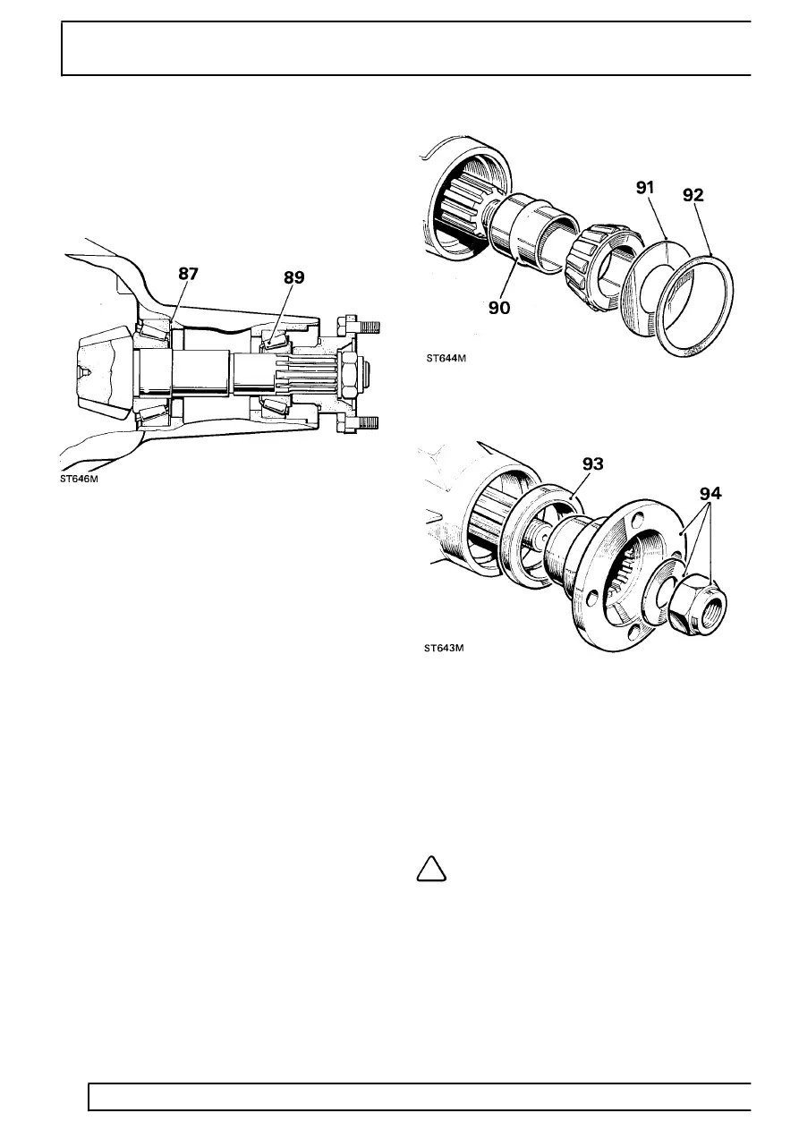
87. Adjust shim thickness under pinion inner cup as
necessary, by amount determined in instructions
85 and 86.
88. Recheck pinion height setting instructions 82 to
84. If setting is correct, mean reading on dial
gauge will agree with figure marked on pinion
end face. For example, with an end face marking
of +3, dial gauge reading should indicate that
pinion is 0.003 in (0.0762 mm) below nominal.
89. When pinion setting is satisfactory, temporarily
remove pinion outer bearing.
90. Fit a new collapsable bearing spacer, flared end
outward, to drive pinion and refit outer bearing.
91. Fit pinion oil slinger.
92. Fit oil seal gasket.
93. Fit pinion oil seal, lipped side first, using general
purpose grease or, where available, a
molybdenum disulphide based grease on seal
lip, using LRT-51-002 to drift in seal.
94. Fit coupling flange and plain washer and loosely
fit a new flange nut. Secure LRT-51-003 to
coupling flange, using slave fixings.
95. Alternately tighten flange nut and check drive
pinion resistance to rotation until following
figures are achieved, as applicable:
A. Assemblies re-using original pinion bearings:
17,3 to 34,5 kgf cm.
B. Assemblies with new pinion bearings: 34,5 to
46,0 kgf cm.
NOTE: Once the bearing spacer has
started to collapse the torque resistance
build-up is rapid, therefore check
frequently, using a spring balance, to ensure the
correct figures are not exceeded, otherwise a new
collapsable bearing spacer will be required.