skoda Workshop Repair Guides

Skoda Workshop Service and Repair Manuals

Removing and installing, tightening the toothed belt|Install > < Removing and installing, tightening the toothed belt
Removing
Removing
   
–  Remove engine cover. To do so pull the front and rear engine cover upwards with a sudden motion.
–  Remove V-ribbed belt → Chapter.
–  Remove top toothed belt guard and cylinder head cover.
–  Remove vacuum pump for brake servo unit → Chapter.
Engine installed in the vehicle
  S10-0115
–  Position crankshaft on TDC for cylinder 1.
The marking on the flywheel -1- must be flush with the marking on the gearbox -2-.
Here one must view from the marking on the flywheel -1- vertically (90°) to the milled surface on the gearbox -A-.
  Note
The valves for cylinder 1 must be closed and the valves for cylinder 4 must overlap.
With the engine removed
  S13-0224
–  Screw the adjusting device -MP1-313- into the threaded bore of the top starter screw.
–  Set adjusting device to 120 mm -arrow A-. The left notch on the vernier is the reference point.
–  Rotate crankshaft until the TDC marking on the flywheel corresponds with the tip of the adjusting device -arrow B-.
  Note
The valves for cylinder 1 must be closed and the valves for cylinder 4 must overlap.
Continued
  S13-0227
–  Lock the camshaft with the camshaft straightedge -MP1-312-.
  Note
The valves for cylinder 1 must be closed and the valves for cylinder 4 must overlap.
–  Centre camshaft straightedge as follows:
   Turn locked camshaft in such a way that one end of the camshaft straightedge strikes the cylinder head. Measure the resulting clearance at the other end of the camshaft straightedge with a feeler gauge.
Insert feeler gauge with halved value between the camshaft straightedge and the cylinder head. Now turn the camshaft in such a way that the camshaft straightedge is positioned on the feeler gauge.
Slide in the second feeler gauge with the same dimension at the other end between the camshaft straightedge and the cylinder head.
  S13-0207
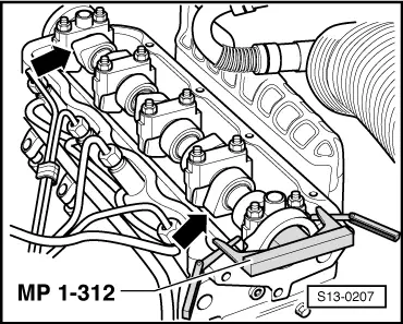
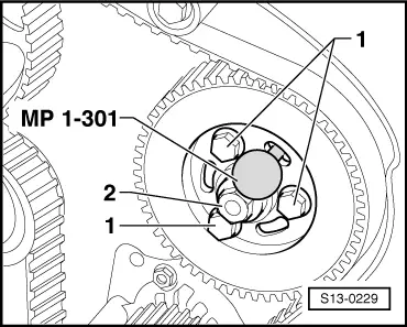
–  Lock injection pump gear with locking pin -MP1-301-.
  Note
If the injection pump gear cannot be correctly locked, first slacken the toothed belt.
–  Determine the version of the injection pump gear Pos. 18.
Injection pump gear 038 130 111 A
–  Release the fixing bolts -1- of the injection pump gear and loosely screw the new bolts to the hub.
Injection pump gear 038 130 111 B
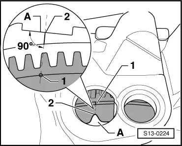
–  Loosen fixing bolts -1- of the injection pump gear.
Proceed as follows for both injection pump gears
  Note
The nut -2- for the hub must never be loosened. Basic setting up of the injection pump cannot be undertaken using normal workshop tools.
  S13-0229
–  Install supporting device -MP9-200- and support engine in fitting position.
  S13-0225
–  Remove engine mounting -arrows A and B-.
–  Remove the noise insulation.
–  Unscrew engine support bracket from cylinder block.
  Note
The engine with the supporting device must be slightly raised in order to remove the engine support bracket. The bottom bolt remains in the support.
–  Remove belt pulley.
–  Remove bottom and middle timing belt guard.
–  Mark the rotation direction of the timing belt.
–  Slacken tensioning pulley.
–  Removing the timing belt from the pulleys.
  S13-0226

Removing and installing, tightening the toothed belt|Install > < Removing and installing, tightening the toothed belt