
Octavia Mk1
 Note
Note
| 1 - | 10 Nm |
| 2 - | Inlet camshaft |
| q | Inspecting axial play → Chapter |
| q | Removing and installing camshafts → Chapter |
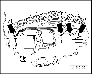
| 3 - | Drive chain |
| q | check for wear |
| q | mark running direction (installed position) before removing → Chapter |
| 4 - | Camshaft adjuster |
| q | with camshaft adjustment valve 1 -N205- |
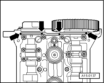
| q | Seal the joints between the camshaft adjuster/cylinder head → Fig. |
| q | removing and installing → Chapter |
| 5 - | rubber metal seal |
| q | replace → Chapter |
| 6 - | Cylinder head |
| q | removing and installing → Chapter |
| q | reworking valve seats → Chapter |
| q | inspecting valve guides → Chapter |
| q |
| 7 - | Exhaust valve |
| q | with a sodium filling |
| q | Observe specifications for disposing of the valves with a sodium filling → Chapter |
| q | do not rework, only grinding in is permissible |
| q | Valve dimensions → Chapter |
| q | inspecting valve guides → Chapter |
| q | reworking valve seats → Chapter |
| 8 - | Inlet valve |
| q | do not rework, only grinding in is permissible |
| q | Valve dimensions → Chapter |
| q | inspecting valve guides → Chapter |
| q | reworking valve seats → Chapter |
| 9 - | Gasket ring |
| q | for inlet camshaft |
| q | replace → Chapter |
| q | pay attention to different version → Chapter |
| 10 - | Trim for hall sender |
| q | check fitting position: |
| Insert the peg in the notch of the camshaft |
| 11 - | Washer |
| q | with cone |
| q | Check fitting position |
| 12 - | 25 Nm |
| 13 - | Hall sender -G40- |
| 14 - | 10 Nm |
| 15 - | 65 Nm |
| q | to release and tighten use counterholder -MP1-216 (3036)- |
| 16 - | Camshaft sprocket |
| q | for exhaust camshaft |
| q | check fitting position: |
| the small stay on the camshaft sprocket points outwards and the TDC marking on the cylinder 1 is visible from the front |
| 17 - | Gasket ring |
| q | for exhaust camshaft |
| q | replace → Chapter |
| q | pay attention to different version → Chapter |
| 18 - | Valve stem seal |
| q | replace → Chapter |
| 19 - | Valve spring |
| q | removing and installing → Chapter |
| 20 - | Valve spring retainer |
| 21 - | Valve collets |
| 22 - | Hydraulic bucket tappets |
| q | do not interchange |
| q | oil contact surfaces |
| q | lay aside with contact surface facing down |
| q | before installing check axial play of the camshaft → Chapter |
| q | check → Chapter |
| q | removing and installing → Chapter |
| 23 - | Bearing cap/inlet camshaft |
| q | must be positioned on the dowel sleeves in the cylinder head |
| q | Check fitting position |
| q | order of installation → Chapter |
| 24 - | Double bearing cover |
| q | must be positioned on the dowel sleeves in the cylinder head |
| q | Seal the joints between the double bearing cap/cylinder head → Fig. |
| q | apply sealant - D 454 300 A2- lightly on the sealing surface before installing → Chapter |
| 25 - | Bearing cover/exhaust camshaft |
| q | must be positioned on the dowel sleeves in the cylinder head |
| q | Check fitting position |
| q | order of installation → Chapter |
| 26 - | Exhaust camshaft |
| q | removing and installing → Chapter |
|
|
|
|