skoda Workshop Repair Guides

Skoda Workshop Service and Repair Manuals

Exhaust system > < Removing and installing engine control unit-J248-
Removing and installing the unit injector
Special tools and workshop equipment required
t  Extractor -T10055-
t  Universal dial gauge holder -MP3-447 (VW 387)-
t  Dial gauge
t  Counterholder -T10172 -, or -MP1-216 (3036)-
Removing
–  Remove top toothed belt guard and cylinder head cover → Chapter.
  Note
Turn engine at hexagonal of central screw at front end of the crankshaft, if necessary using counterholder -T10172 - or using counterholder -MP1-216 (3036)- at camshaft sprocket.
–  Turn the crankshaft until the cam pair of the relevant unit injector to be removed points uniformly upwards.
   
–  Release the counternuts of the adjusting screws -1- and unscrew the adjusting screws until the relevant valve lever rests against the tappet spring of the unit injector.
–  Screw out the fixing screws -2- for the valve-lever shaft from the outside to the inside and remove the valve-lever shaft.
  S23-0184
–  Set the camshaft in such a way that the injection cam for Cylinder 2 points in -direction of arrow-. All clamping pads can be removed in this position.
–  Separate the connector from the unit injector. Support the opposite side of the connector with your finger in order to avoid twisting the connector.
–  Screw out fixing screw -3- of the clamping pad and remove the pad in the direction towards the camshaft.
  S23-0157
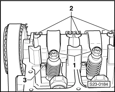
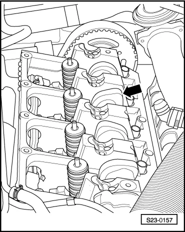
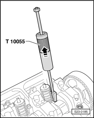
–  Insert extractor -T10055- in direction of the camshaft instead of the clamping pad in the slot of the unit injector.
–  Remove the unit injector through movements of the sleeve at the nut up to the stop in -direction of arrow-.
  Note
Do not interchange the unit injectors, if necessary mark the assignment to each cylinder.
Install
  Note
t  Pay attention to the different version of the unit injector, adjusting screw and ball pin. When replacing the unit injector, the versions are to be replaced individually.
t  The associated adjusting screws in the valve-lever should be replaced when a new unit injector is being installed.
t  For any work procedure involving an adjustment of the unit injector it is necessary to clean the adjusting screw in the valve lever and also the ball pin of the unit injector and to check them for traces of wear. If there is any wear replace the ball pin and the adjusting screw.
t  On the old version of the pump-nozzle drive grease the contact surfaces between ball pins and adjusting screw using grease -G 000 100-.
t  New unit injectors are supplied with O-rings, heat-protection seal and circlip.
–  Before installing the unit injector check the correct position of all three O-rings, heat-protection seal and the circlip.
  Note
The O-rings must not be twisted in the slots.
–  Oil the O-rings and place the unit injector with the greatest of care into the cylinder head.
–  Slide unit injector into the cylinder head seat up to the stop by exerting a uniform pressure.
–  Place the clamping pad in the side slot of the unit injector.
  Note
If the unit injector is not perpendicular to the clamping pad the fixing screw may loosen and cause damage to the unit injector or cylinder head.
Align the unit injector as follows:
–  Screw the clamping pad with the new fixing screw until the unit injector can still easily be turned.
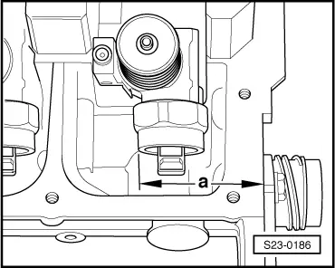
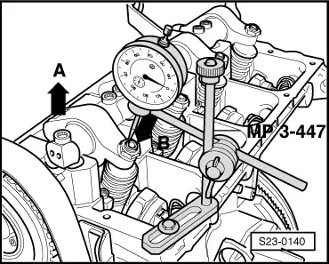
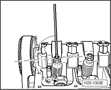
–  Set unit injector at a right angle to the bearing shell of the camshaft.
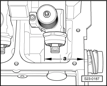
–  Using a caliper gauge, check dimension -a- from the outer side of the cylinder head to the cylinder surface of the unit injector.
  Note
Sliding use of the unit injectors with a new solenoid valve nut. A mixed lining is admissible when one maintains dimension -a-.
  S23-0185
Removing and installing the unit injector with the old solenoid valve nut
  S23-0186
CylinderDimension -a-
1332,2 ± 0.8 mm
2244,2 ± 0.8 mm
3152,8 ± 0.8 mm
464,8 ± 0.8 mm

   
Removing and installing the unit injector with the new solenoid valve nut
  S23-0187
CylinderDimension -a-
1333,0 ± 0.8 mm
2245,0 ± 0.8 mm
3153,6 ± 0.8 mm
465,6 ± 0.8 mm

–  Adjust the unit injector as required, tighten the fixing screw using a torque of 12 Nm and then turn through a further 270° (3/4 of a turn). Tightening may occur in successive stages.
–  Mount valve-lever shaft and tighten up the new fixing screws as follows:
First tighten the inside screws and then the two outside screws by hand. In the same sequence tighten to 20 Nm and turn a further 90 ° (1/4 turn).
Setting
   
–  Place a dial gauge on the adjusting screw of the unit injector.
  Note
Turn engine at hexagonal of central screw at front end of the crankshaft, if necessary using counterholder -T10172 - or using counterholder -MP1-216 (3036)- at camshaft sprocket.
–  Turn the crankshaft in the running direction of the engine until the roller of the valve lever is on the drive cam tip.
t  Roller side -arrow A- is on the highest point.
t  Dial gauge -arrow B- is on the lowest point.
–  Remove the dial gauge.
–  Turn the adjusting screw in the valve lever until one feels a significant resistance increase (the unit injector is against the stop).
  S23-0140
–  Turn the adjusting screw in the opposite direction from the stop by 180° (1/2 turn).
–  Firmly hold the adjusting screw in this position and tighten up the lock nut using a torque of 30 Nm.
–  Place connector onto the unit injector and install the cylinder head cover and the top timing belt cover.
  N23-10092

Exhaust system > < Removing and installing engine control unit-J248-