vauxhall Workshop Repair Guides

Vauxhall Workshop Service and Repair Manuals

Front Valve Body, Disassemble and Assemble (AF 17) > < Rear Valve Body, Disassemble and Assemble (AF 13-II)

Valve Body, Disassemble and Assemble (AF 17)

Note:   The valve body should only be disassembled for cleaning purposes as the individual parts are not available from suppliers.

  Remove

Remove valve body – see operation "Valve Body, Remove and Install (Transmission Removed) (AF 17)".

Survey

1. Solenoid valve for neutral switching
2. Solenoid Valve Retaining Clamp – Converter Clutch
3. Front valve body
4. Front valve body plate
5. Converter clutch solenoid valve
6. Pressure regulator
7. Solenoid valve, 2/3 shift
8. Solenoid valve for 1/2 3/4 shift

Object Number: 2414111  Size: DEFAULT

9

Fluid strainer

10

Lock ball

11

Rear valve body No. 1

12

Non-return valve with spring

13

Rear valve body No. 3

14

Gasket No. 3 behind valve body

15

Plate behind valve body No. 3

16

Switch valve

17

Gasket No. 2 behind valve body

18

Rear valve body plate

19

Gasket No. 1 behind valve body

20

Pressure regulator valve with spring

21

Centre valve body

22

Pressure regulator valve with spring

23

Gasket No. 2 behind front valve body

24

Gasket No. 1 behind front valve body

25

Front valve body cover

26

Front valve body cover

27

Valve body fastening bolt


Object Number: 2414111  Size: DEFAULT

  Disassemble

Remove control valve (1) from valve body.

Remove solenoid valve neutral switch (2).

Remove fastening bolt (3) for converter clutch solenoid valve retaining clamp (4).

Remove converter clutch solenoid valve (5).

Remove 8 fastening bolts (arrows) and wiring harness retaining clamps (10 and 11).

Remove press regulator retaining clamp (6) and pressure regulator (7).

Remove 2/3-way solenoid valve shift mechanism (8) and 1/2- and 3/4-way solenoid valve shift mechanism (9).

Object Number: 2414112  Size: DEFAULT

Remove 8 fastening bolts (arrows) and detach cover of front valve body with gasket.

Remove fluid strainers (1 and 2).

Remove fastening bolts (3) and detach front valve body.

Remove front valve body plate (5) and front valve body gasket No. 2 (4) and front valve body gasket No. 1 (4).

Remove lock ball (8) and pressure regulator valve (6) with spring (7).

Object Number: 2414113  Size: DEFAULT

Remove fastening bolts (1 and 3).

Remove fluid baffle plate (2) and wiring harness retaining clamp (4).

Turn valve body (arrow).

Remove 5 fastening nuts (arrows).

Remove rear valve body No. 2 (6) with rear valve body plate (5) and rear valve body gasket No. 3 (7).

Object Number: 2414114  Size: DEFAULT

Remove fastening bolts (1).

Remove rear valve body No. 1 with valve body plate and gaskets No. 1 and No. 2 of rear valve body.

Use rear valve body No. 1 and remove valve body plate (2) and gasket nos. 1 and 2 of the rear valve body (3).

Remove fluid strainer (5).

Remove lock balls (4 and 6).

Remove pressure regulator valves (7 and 8).

Remove fluid cooler by-pass valve (9) with spring (10) from centre valve body.

  Inspect

Check all parts for wear or damage and replace valve body if necessary.

Object Number: 2414115  Size: DEFAULT

  Assemble

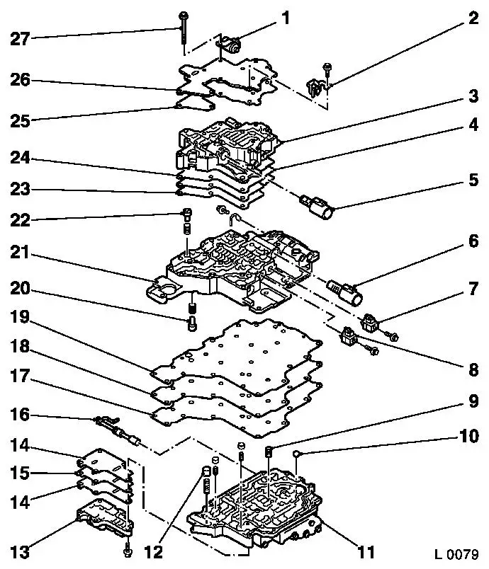
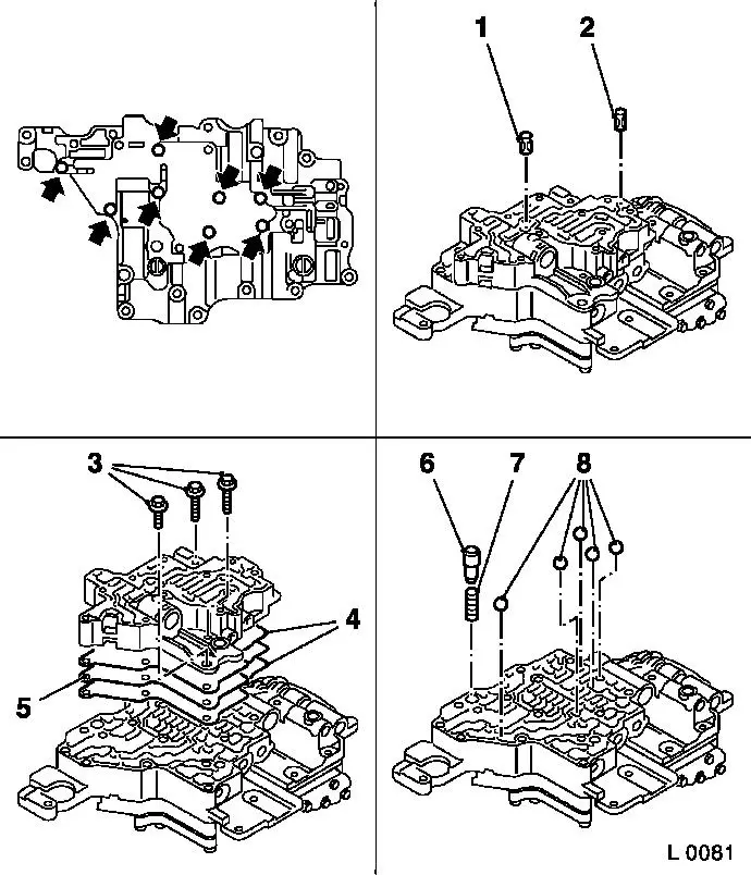
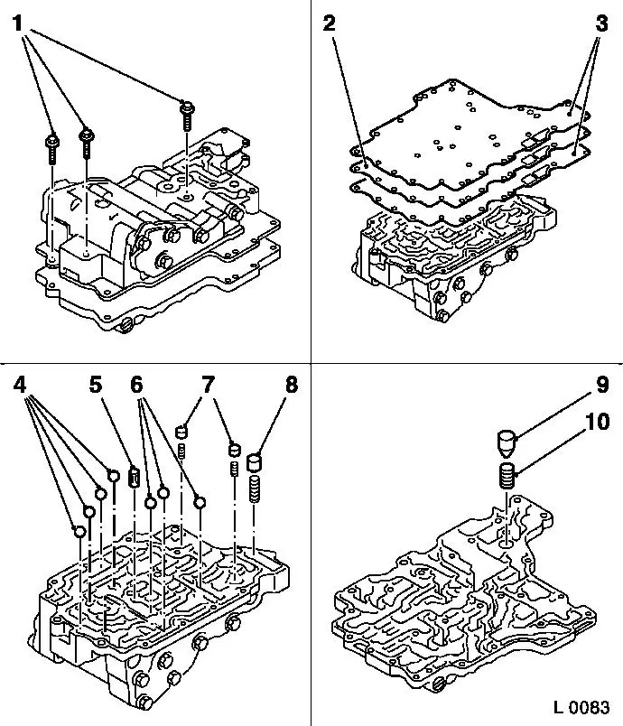
Insert fluid cooler by-pass valve (2) with spring (1) in centre valve body.

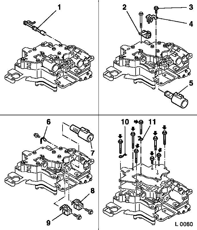
Remove pressure regulator valves (6 and 7).

Remove lock balls (3 and 5).

Remove fluid strainer (4).

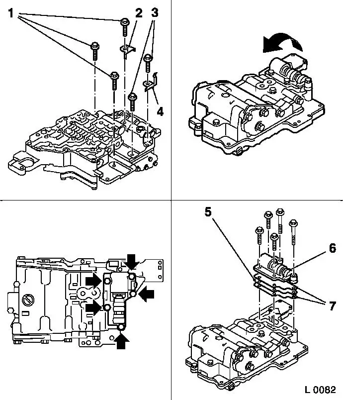
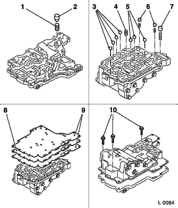
Insert valve body plate (8) and gaskets No. 1 and No. 2 of rear valve body (9) into rear valve body No. 1.

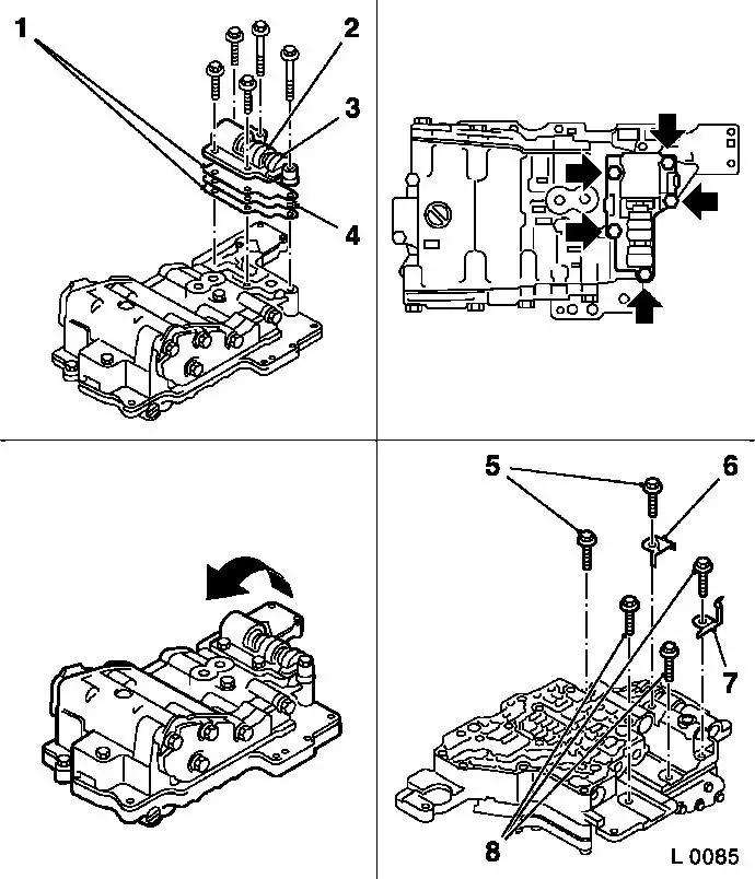
Turn rear valve body No. 1.

Attach rear valve body No. 1 to centre valve body with 3 fastening bolts (10) – tightening torque 7 Nm / 5 lbf. ft.

Caution

Handle all parts carefully as the individual parts are not available from suppliers.

Object Number: 2414116  Size: DEFAULT

Attach rear valve body No. 2 (3) with plate of rear valve body (4) and gasket No. 3 (1) to rear valve body.

Attach 5 fastening bolts (arrows) – tightening torque 7 Nm / 5 lbf. ft.

Turn valve body.

Install fluid baffle plate (6) and wiring harness retaining clamp (7).

Install fastening bolts (5 and 8) – tightening torque 7 Nm / 5 lbf. ft.

Object Number: 2414117  Size: DEFAULT

Insert lock balls (3) and pressure regulator valve (2) with spring (1) in valve body.

Place front valve body plate (6) and gasket No. 2 of front valve body (5) and gasket No. 1 of front valve body (5) on front valve body.

Attach front valve body to centre valve body with fastening bolts (4).

Insert fluid strainers (7 and 8).

Insert 8 fastening bolts (arrows) in front valve body.

Object Number: 2414118  Size: DEFAULT

Attach cover of front valve body with gasket and 8 fastening bolts (arrows) and wiring harness retaining clamp (1 and 2) to front valve body – tightening torque 7 Nm / 5 lbf. ft.

Install 2/3-way solenoid valve shift mechanism (5) and 1/2 2/4-way solenoid valve shift mechanism (6) – tightening torque 7 Nm / 5 lbf. ft.

Attach pressure regulator fastening clamp (3) and pressure regulator (4) – tightening torque 7 Nm / 5 lbf. ft.

Insert converter clutch solenoid valve (10).

Fit fastening bolt (8) for converter clutch solenoid valve retaining clamp (9) – tightening torque 7 Nm / 5 lbf. ft.

Attach solenoid valve neutral switch (7) – tightening torque 7 Nm /5 lbf. ft.

Insert shift valve (11) in valve body.

Object Number: 2414119  Size: DEFAULT

  Install

Install valve body in transmission – see operation "Valve Body, Remove and Install (Transmission Removed) (AF 17)".


Related Literature Units
-
-
-

Front Valve Body, Disassemble and Assemble (AF 17) > < Rear Valve Body, Disassemble and Assemble (AF 13-II)