vauxhall Workshop Repair Guides

Vauxhall Workshop Service and Repair Manuals

Selector Lever Assembly, Remove and Install (Adjustable Steering Column Assembly) > < Steering Wheel, Remove and Install (Vehicles with Airbag)

Steering Column Assembly, Remove and Install (Non-adjustable Steering Column Assembly)

  Remove

Remove steering wheel – see operation "Steering Wheel, Remove and Install (Vehicles with Airbag)".

Detach fastening bolts (1) from upper part of signal switch panelling and detach upper part of signal switch panelling from lower part of signal switch panelling.

Detach fastening bolts (2 and arrow) from under part of signal switch panelling. remove lower part of signal switch panelling.

Vehicles with airbag: Remove contact unit – see operation "Contact Unit, Remove and Install" in group "C".

Unclip turn signal- and wiper switch from bracket.

Remove steering and ignition lock cylinder – see operation "Steering and Ignition Lock Cylinder, Remove and Install" in group "N".

Object Number: 2397912  Size: DEFAULT

Remove immobiliser control unit – see operation "Immobiliser Control Unit, Remove and Install" in group "J".

Withdraw steering and ignition lock contact part downwards and away from casing.

Remove footwell panelling and air distribution duct on driver's side.

Remove upper clamp bolt from intermediate shaft. Compress intermediate shaft lightly and withdraw from steering shaft.

Release clamp bolt, (1) on the steering column bracket.

Remove steering column fastening bolts (2) from crossmember.

Carefully remove steering column assembly – ensure that attaching parts and wiring harness are not damaged.

Object Number: 2397913  Size: DEFAULT

Caution

For vehicles up to MY '99, note TI-C-4, M-23 without fail before installing the steering column assembly in order to avoid damaging the lower steering column bearing.

  Install

Insert steering column assembly and attach to cross-strut with fastening bolts (2) – tightening torque 22 Nm / 16 lbf. ft.

Tighten clamp bolt (1) to steering column bracket – tightening torque 22 Nm / 16 lbf. ft.

Object Number: 2397913  Size: DEFAULT

Push intermediate shaft (3) onto steering shaft – ensure that the steering lock prevents the steering shaft from rotating in the centre position and that the wheels are in the straight-ahead position. Attach upper clamp bolt (1) to intermediate shaft – clean thread and insert clamp bolt with locking compound – tightening torque 22 Nm / 16 lbf. ft.

Caution

Before inserting the clamp bolt make certain that steering shaft groove (arrow) is flush with the intermediate shaft bore hole.

  Install

Reinstall footwell panelling and air distribution duct on driver's side.

Attach contact part for steering/ignition lock to steering/ignition lock housing from below. Install lock cylinder for steering/ignition lock – see operation "Lock Cylinder for Steering/Ignition Lock, Remove and Install" in group "N".

Object Number: 2414694  Size: DEFAULT

Reinstall immobiliser control unit – see operation "Immobiliser Control Unit, Remove and Install" in group "J".

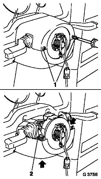
Clip turn signal- and wiper switch onto bracket.

Vehicles with airbag: Install contact unit – see operation "Contact Unit, Remove and Install" in group "C".

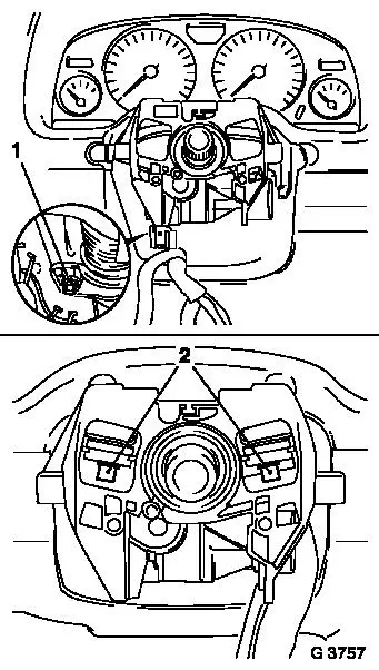
Mount lower part of signal switch panelling (2) using fastening bolts.

Mount upper part of signal switch panelling (1) into lower part of signal switch panelling and attach fastening bolts -ensure that the turn signal and wiper switch dust sleeves are seated correctly.

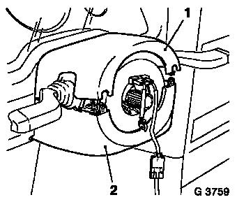
Reinstall steering wheel – see operation "Steering Wheel, Remove and Install (Vehicles with Airbag)". Fastening bolts -ensure that the turn signal and wiper switch dust sleeves are seated correctly.

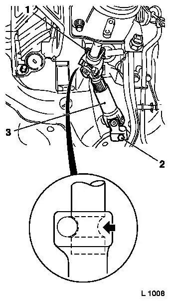
Check straight ahead position, Adjust if necessary – see operation "Straight Ahead Position Check/Adjust".

Object Number: 2397915  Size: DEFAULT


Related Literature Units
-
-
-
-
-
-
-
-
-
-
-
-

Selector Lever Assembly, Remove and Install (Adjustable Steering Column Assembly) > < Steering Wheel, Remove and Install (Vehicles with Airbag)