Inlet Manifold Replacement - without Start/Stop System
Removal Procedure
- Open the bonnet.
- Disconnect the battery negative cable. Refer to
Battery Negative Cable Disconnection and Connection .
- Remove the engine sight shield. Refer to
Engine Sight Shield Replacement .
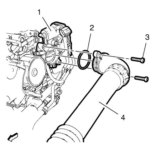
- Remove the 2 charge air cooler outlet air hose
bolts (3).
- Remove the charge air cooler outlet air hose bolt from
the radiator inlet hose bracket.
- Remove the charge air cooler outlet air hose (4)
from the throttle body (1) and hang aside.
- Remove the charge air cooler outlet air hose
seal (2).
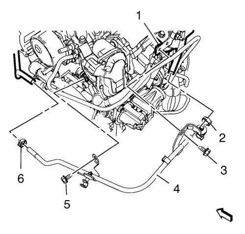
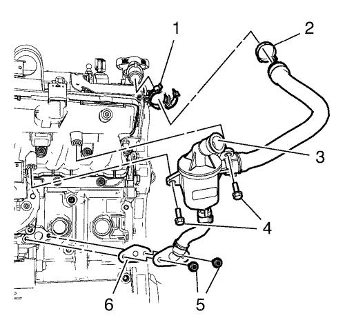
- Remove the 2 exhaust pressure pipe clamp (2,
6).
- Remove the exhaust pressure pipe bolt (5) from
the throttle body support.
- Remove the exhaust pressure pipe bolt (3) from
the exhaust pressure sensor bracket (1).
- Unclip the vacuum hose from the exhaust pressure
pipe (4).
- Remove the exhaust pressure pipe (4).
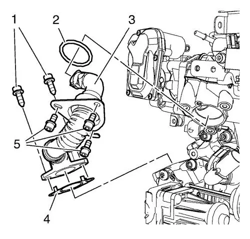
- Remove the 2 exhaust gas recirculation pipe
bolts (1) from the exhaust gas recirculation valve
cooler.
- Remove the 3 exhaust gas recirculation pipe
bolts (5) from the exhaust manifold.
- Remove the exhaust gas recirculation
pipe (3).
- Remove the exhaust gas recirculation pipe
seal (2).
- Remove the exhaust gas recirculation pipe
gasket (4).
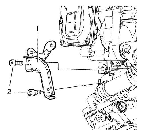
- Remove the 2 throttle body support
bolts (2).
- Remove the throttle body support (1).
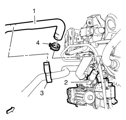
- Unclip the heater inlet hose (1) from the heater
outlet hose (3).
- Remove the heater outlet hose clamp (4).
- Remove the heater outlet hose (1) from the
exhaust gas recirculation valve cooler (2).
- Disconnect the exhaust gas recirculation valve wiring
harness plug.
- Disconnect the exhaust gas recirculation valve
actuator wiring harness plug.
- Remove the exhaust gas recirculation valve actuator
vacuum hose.
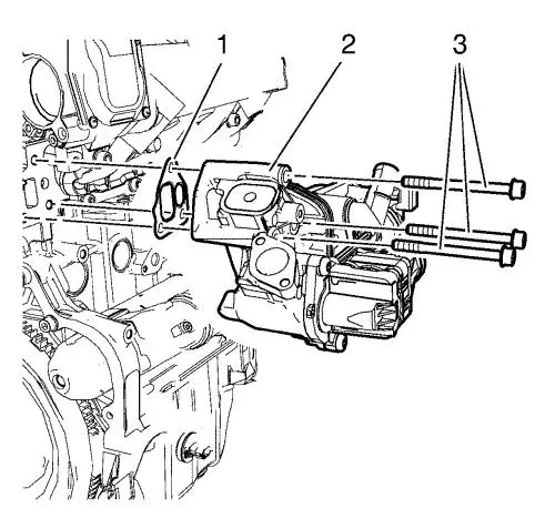
- Remove the 3 exhaust gas recirculation valve
cooler bolts (3).
- Remove the exhaust gas recirculation valve
cooler (2).
- Remove the exhaust gas recirculation valve cooler
gasket (1).
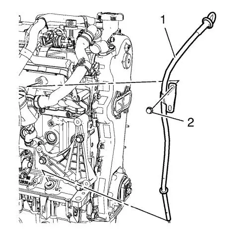
- Unclip the wiring harness from oil level indicator
tube (1).
- Remove the oil level indicator
- Remove the oil level indicator tube
bolt (2).
- Remove the oil level indicator tube (1)
- Remove the oil level indicator gasket from the
cylinder block.
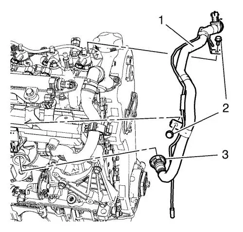
- Disconnect the positive crankcase ventilation pipe
connector (3) from the positive crankcase ventilation oil
separator.
- Disconnect the positive crankcase ventilation pipe
connector wiring harness plug.
- Remove the vacuum hose from the turbocharger wastegate
actuator vacuum control solenoid valve.
- Remove the 2 positive crankcase ventilation pipe
bracket bolts (2).
- Remove the positive crankcase ventilation
pipe (1).
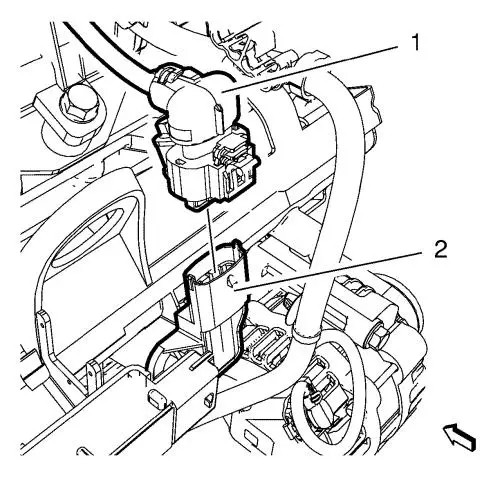
- Unclip the positive crankcase ventilation oil
separator hose from the hose clamp (1).
- Remove the positive crankcase ventilation oil
separator hose clamp (2).
- Remove the positive crankcase ventilation oil
separator hose from the oil filler tube.
- Remove the 2 positive crankcase ventilation oil
separator bolts (4).
- Remove the 2 positive crankcase ventilation tube
bolts (5).
- Remove the positive crankcase ventilation oil
separator (3).
- Remove the positive crankcase ventilation tube
gasket (6).
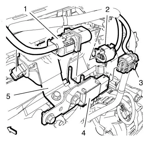
- Disconnect the oxygen sensor wiring harness
plug (2).
- Disconnect the exhaust pressure sensor wiring harness
plug (3) from the exhaust pressure sensor (4).
- Unclip the oxygen sensor wiring harness (1) from
the exhaust pressure sensor bracket (5).
- Disconnect the manifold absolute pressure sensor
wiring harness plug (1) from the manifold absolute pressure
sensor (2).
- Unclip the wiring harness from the intake manifold
bracket.
- Disconnect the throttle body wiring harness plug.
- Unclip the fuel feed pipe and fuel return pipe from
the intake manifold.
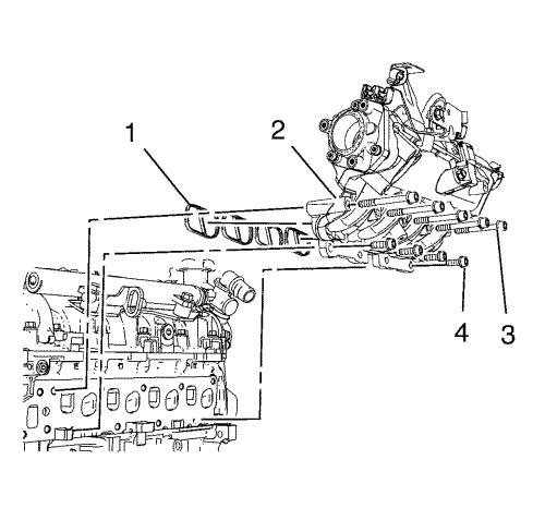
- Remove the 5 intake manifold upper
bolts (3).
- Remove the 4 intake manifold lower
bolts (4).
- Remove the intake manifold (2).
- Remove the 4 inlet manifold
gaskets (1).
- Remove the throttle body assembly. Refer to
Throttle Body Assembly Removal .
- Disassemble the intake manifold. Refer to
Inlet Manifold Disassemble .
Installation Procedure
- Assemble the intake manifold. Refer to
Inlet Manifold Assemble .
- Install the throttle body assembly. Refer to
Throttle Body Assembly Installation .
- Install the 4 NEW intake manifold
gaskets (1).
- Install the inlet manifold (2).
Caution: Refer to
Fastener Caution in the Preface
section.
- Install the 4 intake manifold lower
bolts (4) and the 5 intake manifold upper bolts (3)
and tighten to
25 N·m (18 lb ft)
.
- Clip in the fuel feed pipe and the fuel return pipe to
the intake manifold.
- Connect the throttle body wiring harness plug.
- Clip in the wiring harness to the intake manifold
bracket.
- Connect the manifold absolute pressure sensor wiring
harness plug (1) to the manifold absolute pressure
sensor (2).
- Connect the oxygen sensor wiring harness
plug (2).
- Connect the exhaust pressure sensor wiring harness
plug (3) to the exhaust pressure sensor (4).
- Clip in the oxygen sensor wiring harness (1) to
the exhaust pressure sensor bracket (5).
- Install the positive crankcase ventilation tube
gasket (6).
- Install the positive crankcase ventilation oil
separator (3).
- Install the 2 positive crankcase ventilation tube
bolts (5) and tighten to
9 N·m (80 lb in) .
- Install the 2 positive crankcase ventilation oil
separator bolts (4) and tighten to
9 N·m (80 lb in) .
- Install the positive crankcase ventilation oil
separator hose to the oil filler tube.
- Install the positive crankcase ventilation oil
separator hose clamp (2).
- Install the positive crankcase ventilation oil
separator hose to the hose clamp (1).
- Install the positive crankcase ventilation
pipe (1).
- Install the vacuum hose to the turbocharger wastegate
actuator vacuum control solenoid valve.
- Connect the positive crankcase ventilation pipe
connector wiring harness plug.
- Connect the positive crankcase ventilation pipe
connector (3) to the positive crankcase ventilation oil
separator.
- Install the 2 positive crankcase ventilation pipe
bracket bolts (2) and tighten to
8 N·m (71 lb in) .
- Install a NEW oil level indicator gasket to cylinder
block.
- Install the oil level indicator tube (1)
- Install the oil level indicator tube bolt (2) and
tighten to
9 N·m (80 lb in) .
- Install the oil level indicator .
- Clip in the wiring harness to the oil level indicator
tube (1).
- Install the NEW exhaust gas recirculation valve cooler
gasket (1).
- Install the exhaust gas recirculation valve
cooler (2).
- Install the 3 exhaust gas recirculation valve
cooler bolts (3) and tighten to
22 N·m (16 lb ft)
.
- Install the exhaust gas recirculation valve actuator
vacuum hose.
- Connect the exhaust gas recirculation valve actuator
wiring harness plug.
- Connect the exhaust gas recirculation valve wiring
harness plug.
- Install the heater outlet hose (1) to the exhaust
gas recirculation valve cooler (2).
- Install the heater outlet hose clamp (4).
- Clip in the heater inlet hose (1) to the heater
outlet hose (3).
- Install the throttle body support (1).
- Install the 2 throttle body support
bolts (2) and tighten to
9 N·m (80 lb in) .
- Install a NEW exhaust gas recirculation pipe
gasket (4) to the exhaust gas recirculation pipe.
- Install the exhaust gas recirculation pipe
seal (2) to the exhaust gas recirculation pipe.
- Install the exhaust gas recirculation
pipe (3).
- Install the 3 exhaust gas recirculation pipe
bolts (5) to the exhaust manifold and tighten to
9 N·m (80 lb in) .
- Install the 2 exhaust gas recirculation pipe
bolts (1) to the exhaust gas recirculation valve cooler and
tighten to
25 N·m (18 lb ft)
.
- Install the exhaust pressure pipe (4).
- Install the exhaust pressure pipe bolt (3) to the
exhaust pressure sensor bracket (1) and tighten to
9 N·m (80 lb in) .
- Install the exhaust pressure pipe bolt (5) to the
throttle body support and tighten to
9 N·m (80 lb in) .
- Install the 2 exhaust pressure pipe
clamp (2,6).
- Clip in the vacuum hose to the exhaust pressure
pipe (4).
- Install a NEW charge air cooler outlet air hose
seal (2).
- Install the charge air cooler outlet air hose (4)
to the throttle body (1).
- Install the charge air cooler outlet air hose bolt to
the radiator inlet hose bracket and tighten to
10 N·m (89 lb in)
.
- Install the 2 charge air cooler outlet air hose
bolts (3) and tighten to
10 N·m (89 lb in)
.
- Install the engine sight shield. Refer to
Engine Sight Shield Replacement .
- Connect the battery negative cable. Refer to
Battery Negative Cable Disconnection and Connection .
- Close the bonnet.
|
