
FUNCTIOnAL DESCRIPTION
- Make
- Alfa Romeo
- Model
- 145/146 Electrical System Diagnosis Manual, Volume 3
- Year
- 1994–2001
- Section
- Airbag + Sidebag › FUNCTIOnAL DESCRIPTION
FUNCTIOnAL DESCRIPTION
The R22 control unit is protection-powered, (circuit protected by fuse F15 located in fuse box G1) by pin 40.
The power supply of the R22 control unit is protected by another fuse (G395) located in the vicinity of the same fuse box (G1).
The system contains two frontal cushions: one is positioned on the driver's side R23 (in the center of the steering wheel) and one in the dashboard in front of the passenger R27. It contains two side cushions: R32 e R33.
NOTE: The cushion on the steering wheel is connected electrically by means of a spiraled cable and the connector G383.
While the car is traveling, control unit R22 continuously runs system diagnostics to check the continuity of system circuits and components.
In case of a frontal collision detected by the two internal sensors (one piezoelectric and the other mechanical), the control unit, activates both modules by sending a voltage by means of two signals at 12V: one earth signal and one power supply signal, pin 13 and 14 for the passenger module R27 and pin 10 and 11 for the module on the steering wheel R23.
If the sensor R30 (only present up to June '99) indicates (pin 15 and 37 of R22) the absence of the passenger on the seat, the relative airbag is not activated.
In the case of a side collision, the information is sent to the control unit by sensors R31 (driver's side) and R32 (passenger's side) on pins 20 and 22 and 21 and 23 of R22 respectively.
Consequently the control unit enables the side bag on the driver's side R33 (from pins 16 and 17) and the side bag on the passenger's side R34 (from pins 18 and19).
The telltale light in question is the so-called "intelligent" type: in fact it lights up not only when the system detects an anomaly, but also in cases of a lack of connection or short circuit to earth from the circuit that connects the telltale light to the relative control unit, thanks to a special internal pilot circuit which checks proper connection.
Upon detection of a failure or malfunction of the system, the type of failure is memorized and consequently the airbag telltale light on the instrument panel C10 turns on to warn the user that there is a failure in the system.
Finally, connection T3 allows connection to the ALFA TESTER (pin 24).
CONTROL UNIT PIN-OUT
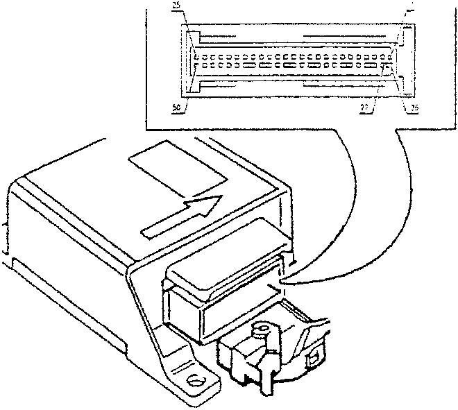
- Airbag system failure warning light signal
- Earth
- Earth
- K diagnostics line
- Activation (+) driver's frontal airbag
- Activation (-) driver's frontal airbag
- Activation (+) passenger's frontal airbag
- Activation (-) passenger's frontal airbag
- Passenger presence sensor signal
- Activation (+) driver's side airbag
- Activation (-) driver's side airbag
- Activation (+) passenger's side airbag
- Activation (-) passenger's side airbag
- Driver's seat side sensor
- Passenger's seat side sensor
- Driver's seat side sensor power supply
- Passenger's seat side sensor power supply
- Diagnostics K line earth
- Passenger presence sensor signal
- Protected power supply
Parts & tools for this job For 1994 Alfa Romeo 145/146
- TOOLOBD2 scanner with SRSSearch: OBD2 scanner ABS SRS
- TOOLTrim removal tool kitSearch: trim removal tool kit
Links open Amazon search results in a new tab. As an Amazon Associate I earn from qualifying purchases.