
General description
- Make
- Alfa Romeo
- Model
- 145/146 Electrical System Diagnosis Manual, Volume 3
- Year
- 1994–2001
- Section
- Horns › General description
GENERAL DESCRIPTION
The car horn system is formed of two horns with different tones: one high tone and the other low tone: they are both activated simultaneously.
The horns are operated conventionally pressing the button located in the centre of the steering wheel (versions without airbag) or one of the two switches on the spokes at the side of the airbag cushion (versions with airbag).
For the obvious safety reasons the horns can be activated at all times even if the ignition key is not engaged.
FUNCTIONAL DESCRIPTION
The horns relay switch I3, located in fusebox G1, is supplied by the battery through fuse F2, also in G1.
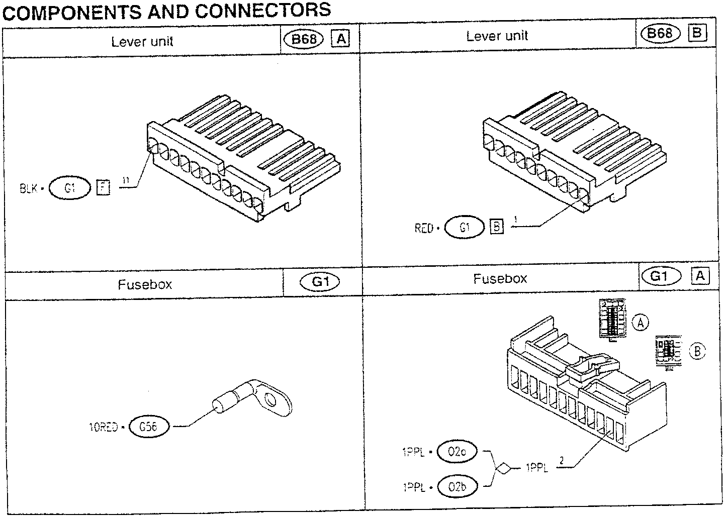
The coil of relay switch I3 is energized with an earth signal leading from the horn control switch which is connected to the lever unit B68 (this connection is made in a special way for the versions with airbag: see "Checking Components").
This way the supply is sent by the relay switch to the horns O2, which are already connected to earth.
COMPONENTS AND CONNECTORS
| Lever unit | B68 A | Lever unit | B68 B |
|---|---|---|---|
|
|||
| Fusebox | G1 | Fusebox | G1 A |
Parts & tools for this job For 1994 Alfa Romeo 145/146
- PARTReplacement bulbsSearch: Alfa Romeo 145/146 1994 bulbs
- TOOLDigital multimeterSearch: automotive digital multimeter
Links open Amazon search results in a new tab. As an Amazon Associate I earn from qualifying purchases.