
General description
- Make
- Alfa Romeo
- Model
- 145/146 Electrical System Diagnosis Manual, Volume 3
- Year
- 1994–2001
- Section
- Sidelights › General description
GENERAL DESCRIPTION
The side lights are turned on when the switch on the lever unit is turned to the first position and only when the ignition key is engaged: this prevents the battery from discharging if the lights are inadvertently left on when leaving the car.
N.B.: They can also be turned on by slightly withdrawing the ignition key and turning it in the opposite direction holding down the special button: key in the "PARKING" position (see also "Power supply").
When the side lights are turned on, the number plate lights and numerous interior lights for lighting the passenger compartment, instruments and controls are also turned on (see "Controls lighting").
A warning light on the instrument panel indicates that the side lights are on.
For safety reasons the circuit is protected by two "crossed" fuses: one for the right front and left rear lights etc., the other for the left front and right rear lights, etc..
FUNCTIONAL DESCRIPTION
The side lights circuit is activated by the corresponding relay switch 164 located in fusebox G1.
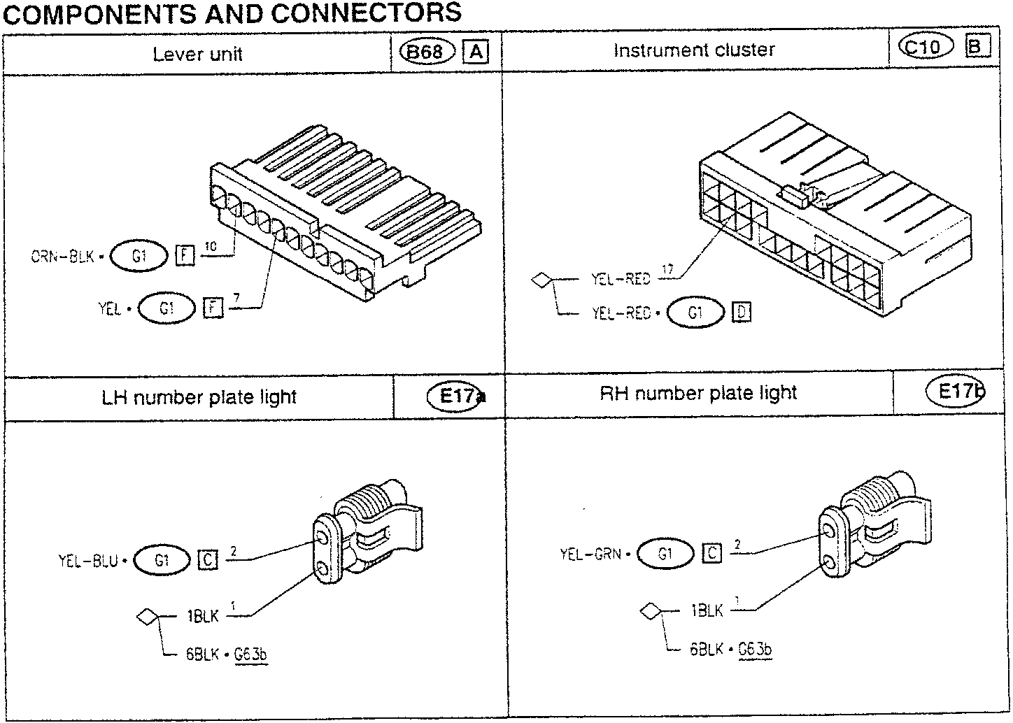
COMPONENTS AND CONNECTORS
| Lever unit | B68 A | Instrument cluster | C10 B | ||
|---|---|---|---|---|---|
| CRN-BLK • G1 F 1C | YEL-RED 17 | YEL-RED • G1 D | |||
| YEL • G1 F 7 | |||||
| LH number plate light | E17a | RH number plate light | E17b | ||
| YEL-BLU • G1 C 2 | YEL-GRN • G1 C 2 | 1BLK 1 | |||
| 6BLK • G63b | 6BLK • G63b | ||||
Moving the switch on the lever unit B68 to position "I" - when the ignition key is engaged the coil of relay switch 164 is supplied thereby closing the circuit that supplies the side lights; this circuit is protected by two fuses of box G1 (box "A" and "B") and by a third fuse still in box G1 "C"; F5 for the right front and left rear lights, F6 for the front left and rear right and fuse F16 - only box "C" - for protecting the services of the steering column lever unit B68. This way the front sidelights E23 (right) and E24 (left), the rear ones E19 (right) and E20 (left) and the number plate lights E17a and E17b.
The supply line of fuse F5 - boxes "A" and "B" or of fuse F6 - box "C" - also sends a signal to the instrument cluster C10 to turn on the corresponding warning light.
When the ignition key is at the "PARKING" position all the side lights are turned on as a direct supply is sent to fuses F5 and F6 in fusebox G1, "by-passing" relay switch 164.
NOTE: Turning the side lights on also supplies numerous other circuits with "consent" signals (e.g. circuits that operate only when the side lights are on) or by supply lines in the real sense of the term (for example by illuminating the ideograms of the various buttons and controls...). The former are described and illustrated in the diagrams relating to the components to which they refer and the latter in the "Controls lighting" section.
Parts & tools for this job For 1994 Alfa Romeo 145/146
- TOOLDigital multimeterSearch: automotive digital multimeter
- PARTAssorted fuse kitSearch: car fuse assortment kit
- TOOLWire crimper and connector kitSearch: wire crimper connector kit
Links open Amazon search results in a new tab. As an Amazon Associate I earn from qualifying purchases.