
Displacement control
- Make
- Alfa Romeo
- Model
- 145/146 Factory Service Manual
- Year
- 1994–1999
- Section
- Heating and ventilation - T. Spark 16V engine › Displacement control
Displacement control
Displacement control is obtained by a pneumatic device incorporated in the compressor, which by-passes part of the gas in the compression stage to the inlet, i.e. into the low pressure chamber.
When this system is activated it reduces the displacement in the compressor gradually and continuously to appr. 17% of the total.
The device comprises a piston (A) which can run in the cylinder (C) countered by the spring (B).
When the piston is positioned as in Fig A, it cuts off the holes (D) which put compartment (E), in which the gas starts being compressed, into communication with the low chamber (F).
Viceversa, when piston (A) is in the position of Fig. B, holes (D) put the two chambers into communication.
The piston is operated by a small amount of pressurised gas, withdrawn by the duct (J) which communicates with the calibrated hole (G).
The pressure regulator (H) is adjusted by the difference in pressure between the intake - chamber (F) - and the delivery: with a high intake pressure, the valve (I) is closed, and the pressure of the gas acts on the piston (A) taking it to the position of Fig.A.
Holes (D) are cut off and by-passing does not take place, and in chamber (E) compression of the gas begins as described later.
When the intake pressure falls, the regulator (H) opens the valve (I) allowing the pressurised gas in the duct (J) and cylinder (C), to discharge into the low pressure chamber (F).
Piston (A) is pushed by the spring (B) allowing the by-pass holes (D) to open.
This way, part of the gas in the chamber (E) - start of compression - can flow into the low pressure chamber (F), until the blade (K), has passed the holes (D); this reduces the amount of gas in the chamber (E) thereby reducing the displacement of the compressor.
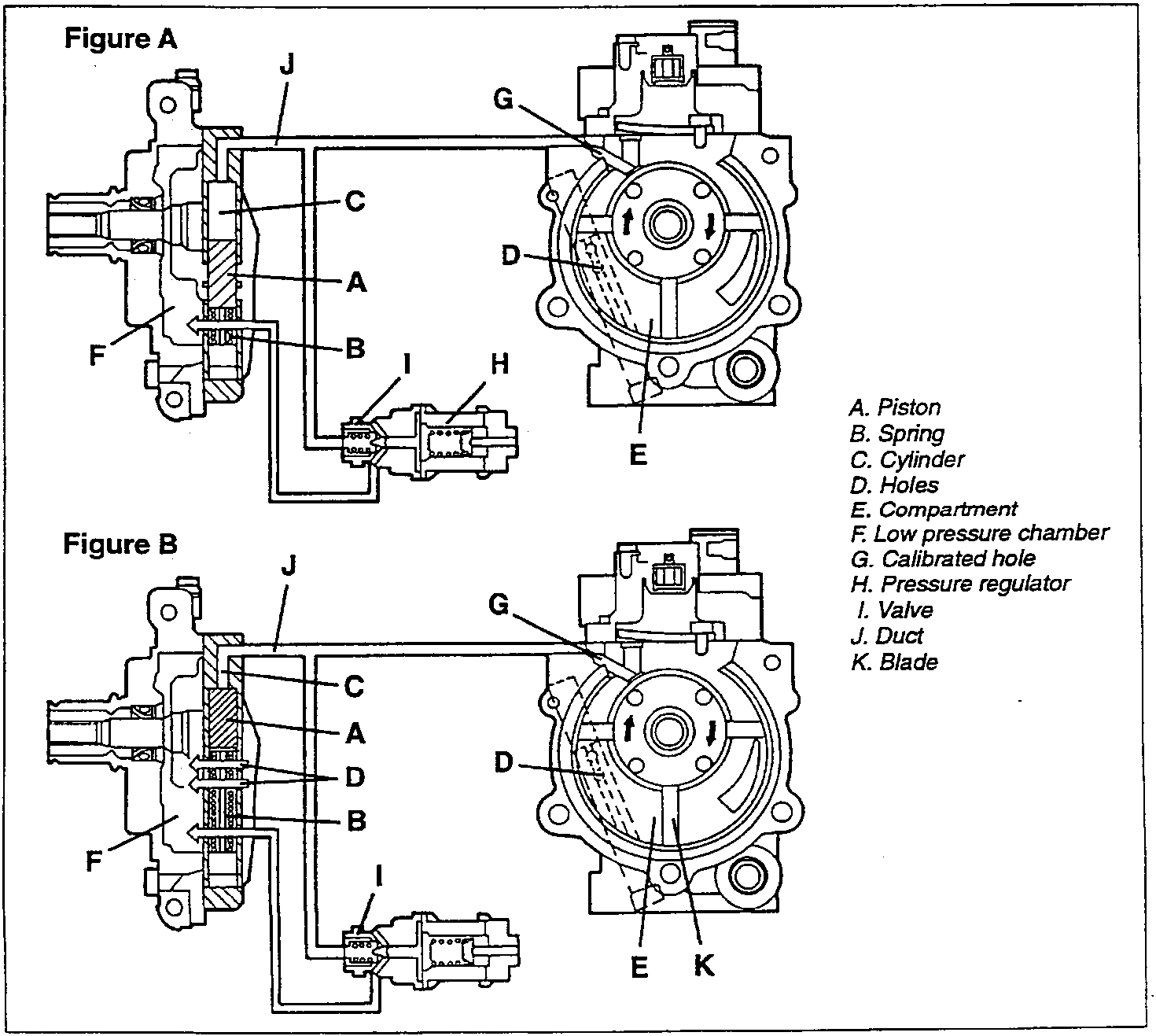
- A. Piston
- B. Spring
- C. Cylinder
- D. Holes
- E. Compartment
- F. Low pressure chamber
- G. Calibrated hole
- H. Pressure regulator
- I. Valve
- J. Duct
- K. Blade
Parts & tools for this job For 1994 Alfa Romeo 145/146
- PARTEngine gasket setSearch: Alfa Romeo 145/146 1994 engine gasket set
- TOOLTorque wrenchSearch: 3/8 inch torque wrench
- TOOLFeeler gauge setSearch: feeler gauge set
Links open Amazon search results in a new tab. As an Amazon Associate I earn from qualifying purchases.