50 Heating, ventilation and air conditioningRe-circulation
With key on STOP proceed as follows:
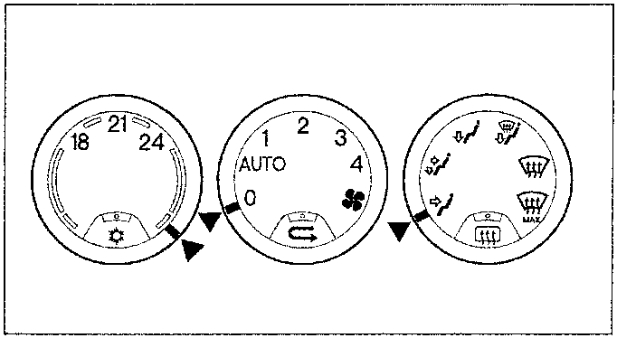
position lever as in figure:
temperature selection lever on “maximum heat”
ventilation selection lever on “0”
flow distribution lever on “frontal flow”
rotate the key to MAR.
within 10 seconds activate the ventilation selection lever setting it to “AUTO”, therefore to “0”, then again to “AUTO”, and finally on “0”.
turn the key to STOP
At this point, the ECU is configured for manual operation. The compressor can be activated by pressing the specific key. This configuration remains for all the following start-ups. Compressor activation is, however, automatic even in this configuration for the “re-circulation” and “rapid demisting” functions.
To return to automatic mode, reverse the sequence indicated in points 1-4.
Re-circulation
The central button operates the air re-circulation function. When the button is pressed, the respective LED lights up. If the key is released “air flows “dynamically” from the outside.
The re-circulation function also automatically activates the air cooling circuit function which can be excluded by pressing the respective button.
Filtering device
The air drawn into the compartment from outside crosses a double layer filter:
the first “particulate” level stops the of small dust particles and pollen
the second “active carbons” level blocks any polluting agents present in the atmosphere.
Heated rear window (Gtv only)
The right hand side button turned on the heated rear window When heated rear window is on the respective LED lights up (for further details refer to Electric system diagnosis)
ECU OPERATING LOGIC CLIMATE CONTROL SYSTEM
Calculation of air capacity and temperature:
The ECU adapts the temperature in the passenger compartment as required as quickly as possible, considering the settings and the temperature conditions. The ECU calculates the best operating parameters (capacity and temperature) of the air in the passenger compartment) by means of certain thermal balance equations considering the heat introduced into the passenger compartment, the wasted heat and numerous thermal factors and coefficients. According to the identified values, the position of the mixing flap and the speed of the electric fans are automatically controlled. The calculation program is repeated every 15 seconds or when a parameter is modified manually.
Enabling air cooling:
The respective button activates the air cooling circuit. The actual activation of the compressor, however, is excluded in the following cases:
external temperature lower than 0° – 2°C (if re-circulation is not on)
passenger compartment temperature lower than 0° – 2°C (if re-circulation is on)
The compressor can be deactivated by the circuit control pressure switch or the engine ECU according to the different types of ECU’s (see engine-specific ignition/injection ECU’s).
Finally (for Spider only) the compressor is disabled by the “top open” signal from the respective switch.
External temperature control signal:
The signal from the external temperature sensor located in the right hand door mirror is “filtered” in a suitable way by the ECU, not considering the values read at low vehicle speed so that values that are distorted, for example, while standing in a queue with the engine running.
Links open Amazon search results in a new tab. As an Amazon Associate I earn from qualifying purchases.
Help keep workshop manuals free
workshop-manuals.com provides free online workshop manuals.
If they helped you fix your car, please consider sharing or
making a small donation to keep the servers running.