
Rearming the Airbags (page 3 of 3)
- Make
- Aston Martin
- Model
- DB7 Factory Workshop Manual Volume 2: Electrics, Body and Air Conditioning
- Year
- 1994–1998
- Section
- Airbag system
ElectricsRearming the Airbags · page 3 of 3
The wiring to the airbag diagnostic module passes through two plugs into a single socket. Plug 1 is grey coloured, plug 2 is black. To aid in fault analysis, the diagnostic module connector pins for plugs 1 and 2, and their functions are listed below:
| Connector 1 - Grey Colour | ||
|---|---|---|
| Pin No. | Colour | Circuit |
| 1-1 | LGS | 12V Ignition Supply |
| 1-2 | ON | RH Crash Sensor Monitor |
| 1-3 | B | Ground |
| 1-4 | YW | Airbag Warning Lamp Output |
| 1-5 | B | Ground |
| 1-6 | YU | LH Crash Sensor Monitor |
| 1-7 | RW | 12V Battery Power |
| 1-8 | - | Not Used |
| 1-9 | RN | Safing Sensor Input |
| 1-10 | RG | Safing Sensor Ground Monitor |
| 1-11 | KU | RH Crash Sensor Feed |
| 1-12 | KG | LH Crash Sensor Feed |
| Connector 2 - Black | ||
|---|---|---|
| Pin No. | Colour | Circuit |
| 2-1 | - | Not Used |
| 2-2 | RP | Passenger Airbag Module Feed |
| 2-3 | KP | Passenger Airbag Module Return |
| 2-4 | KN | Drivers Airbag Module Return |
| 2-5 | RP | Drivers Airbag Module Feed |
| 2-6 | YG | Safing Sensor Output Monitor |
| 2-7 | - | Not Used |
| 2-8 | OP | LH Crash Sensor Ground Monitor |
| 2-9 | OW | RH Crash Sensor Ground Monitor |
| 2-10 | - | Not Used |
| 2-11 | YP | Safing Sensor Feed |
| 2-12 | - | Test Input |
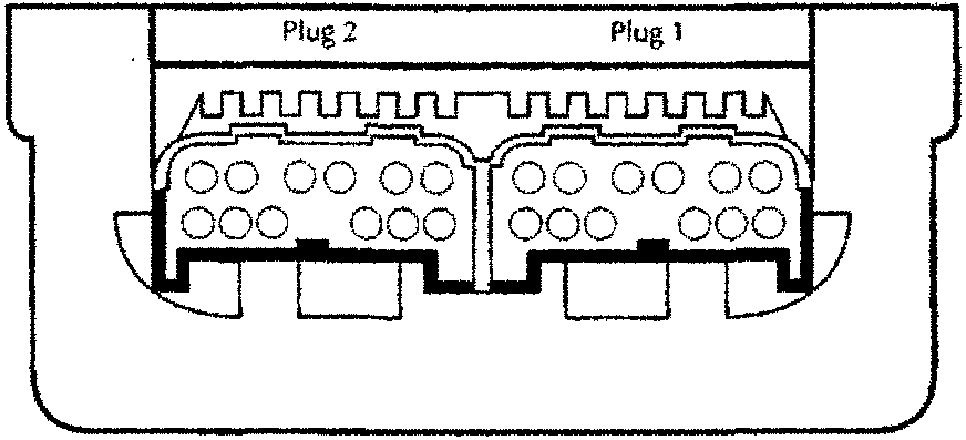
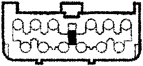
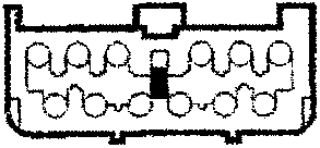
| Connector 2/12-Way/Black | Connector 1/12-Way/Grey | ||||||||||
| 6 YG | 5 RP | 4 KN | 3 KP | 2 RP | - | 6 YU | 5 B | 4 YW | 3 B | 2 ON | LGS |
| 12 - | 11 YP | 10 - | 9 OW | 8 OP | - | 12 KG | 11 KU | 10 RG | 9 RN | 2 - | RW |
| F2 | F3 | ||||||||||
| 6 | - | 12 | 7 | 6 | - | 12 | 7 | ||||
Parts & tools for this job For 1994 Aston Martin DB7
- TOOLOBD2 scanner with SRSSearch: OBD2 scanner ABS SRS
- TOOLTrim removal tool kitSearch: trim removal tool kit
Links open Amazon search results in a new tab. As an Amazon Associate I earn from qualifying purchases.