
Actuators
- Make
- Aston Martin
- Model
- DB9 Factory Workshop Manual
- Year
- Issue 2, 2005
- Section
- Body Ventilation system › Actuators
12 Climate controlActuators
Actuators
| Repair Operation Time (ROT) | |
|---|---|
| Item | Code |
| Actuators Renew | TBA |
- Blower unit
- Air intake actuator
- A/C unit
- Air mode actuator
- Air mix actuator
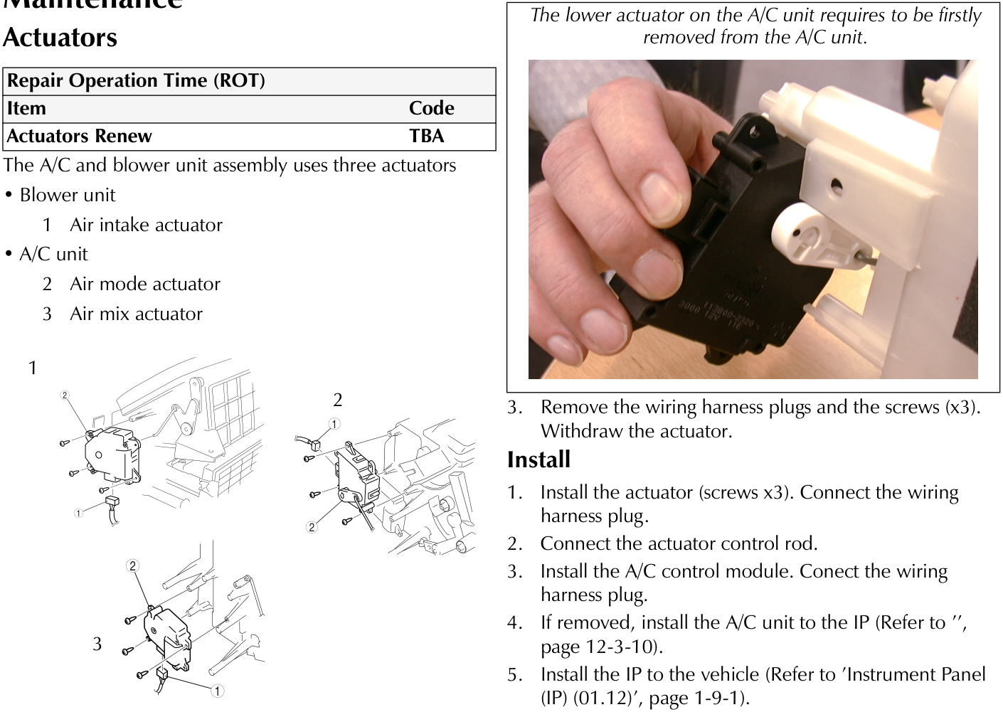
The lower actuator on the A/C unit requires to be firstly removed from the A/C unit.
The removal procedure is the same for all three actuators.
To remove the blower unit actuator remove the A/C unit from the IP (Refer to 'A/C Unit', page 12-3-11).
Removal
- Remove the IP from the vehicle (Refer to 'Instrument Panel (IP) (01.12)', page 1-9-1).
To gain access to the Air mode and Air mix actuators remove the A/C control module (screws x3).
- Disconnect the actuator control rod.
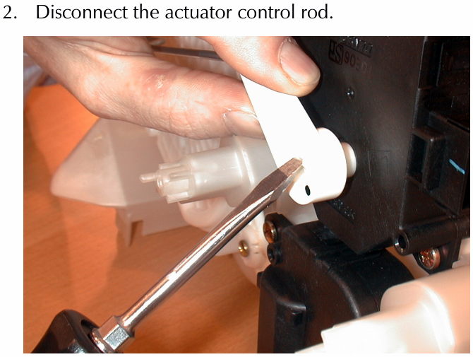
- Remove the wiring harness plugs and the screws (x3). Withdraw the actuator.
Install
- Install the actuator (screws x3). Connect the wiring harness plug.
- Connect the actuator control rod.
- Install the A/C control module. Conect the wiring harness plug.
- If removed, install the A/C unit to the IP (Refer to '', page 12-3-10).
- Install the IP to the vehicle (Refer to 'Instrument Panel (IP) (01.12)', page 1-9-1).
Air Intake Actuator
Inspection
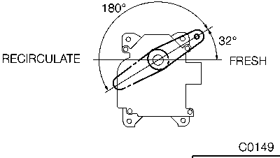
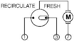
- Connect the battery positive voltage to Intake Actuator terminal 1 (or 3), and ground to terminal 3 (or 1).
- Verify that the Air Intake Actuator operates as shown.
If the operation condition is not normal, replace the Air Intake Actuator.
| Terminal (C0149) | Air Intake Actuator Operation | |
|---|---|---|
| 1 | 3 | |
| Ground | B+ | Fresh > Recirculate |
| B+ | Ground | Recirculate > Fresh |
Parts & tools for this job For 2005 Aston Martin DB9
- TOOLTrim removal tool kitSearch: trim removal tool kit
- PARTTouch-up paintSearch: Aston Martin touch up paint
- PARTPanel clip assortmentSearch: Aston Martin panel clips assortment
Links open Amazon search results in a new tab. As an Amazon Associate I earn from qualifying purchases.